|
| |
TM 9-4120-367-14
TM 07592B-14/1
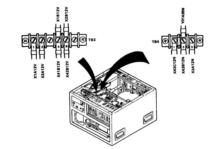
Figure 3-3. Connector J11 Wired at Terminal Board TB3 (Single Phase)
Connector J11,
Single Phase,
Terminal Board
TB3
Connector J11,
Single Phase,,
Terminal Board
TB4
Action
a.
b.
OR
Leads X1B12V and X2B12V must be connected
to terminal board TB3, terminals 4 and 5.
AND
Wire X43B12N must be connected to terminal 2;
wire X3A12N, connected to terminal 3.
Remarks
Power supply connected to
connector J11, single phase.
(Figure FO-1) Replace all re-
moved covers.
3-9
3.5 INSTALLATION OR REMOVAL. - Continued
Location/Item
|