|
| |
ARMY TM 9-4120-381-14
NAVY EE-00-CA-MMA-010/7053-AC
AIR FORCE TO 35E9-136-31
5-49. CRANKSHAFT, PISTONS AND RODS - Continued.
REASSEMBLY - Continued.
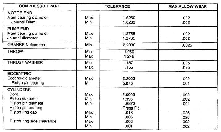
Table 5-4. Compressor Wear Limits (Factory Tolerances In.)
7.
Measure side clearance between ring and piston (6) (Table 5-4).
8.
Check rings (4) and (5) rotate freely.
NOTE
· Use matched pistons and eccentric straps removed in disassembly for assembly if pistons or eccentric
straps are not replaced.
· While installing eccentric shaft and straps, tap shaft lightly and rotate shaft to prevent straps from
jamming.
9.
Install piston and eccentric strap (34) assemblies through bottom plate (21) into cylinder heads (20).
10.
Guide eccentric shaft (7) thru pump end (22) and eccentric straps (34).
NOTE
Counter weights and eccentric strap shields must be reassembled in same position as labeled in disassembly.
11.
Position counterweights (1, 30) and two eccentric strap shields (32, 33) in mounting position.
12.
Install four counterweight and eccentric strap capscrews (35) and locknuts (31) and torque to 8-10 lb-ft.
5-116
|