|
| |
TM 9-4120-389-14
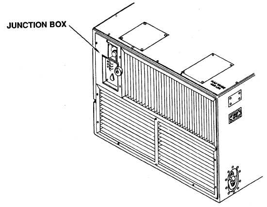
4-45. JUNCTION BOX
Figure 4-47. Junction Box
The junction box contains the majority of relays and terminal boards. Contained therein are the electrical
connector (J1) with leads, terminal boards TB1 and TB2, condenser fan relay (K4), evaporator fan relay (K6),
heater relays (K2 and K5), compressor relay (K3), time delay (K1), transformer (T1), junction box wiring
harness and junction box (housing). See the following paragraphs for junction box parts.
a.
Junction box removal/installation (See Para. 4-46).
b.
Electrical connector (J1) with leads (See para. 4-47).
c.
Terminal boards (TB1 and TB3) (See para. 4-48).
d.
Compressor relay (K3), Condenser fan relay (K4), evaporator fan relay (K6) and heater relays
(K2 and K5)
(See para. 4-49).
e.
Time delay relay (K1)
(See para. 4-50).
4-141
|