 |
|||
|
|
|||
|
|
|||
| ||||||||||
|
|
 TM 9-4120-425-14&P
REMOTE CONTROL MODULE UNIT MAINTENANCE - Continued
0034-00
TEST Continued
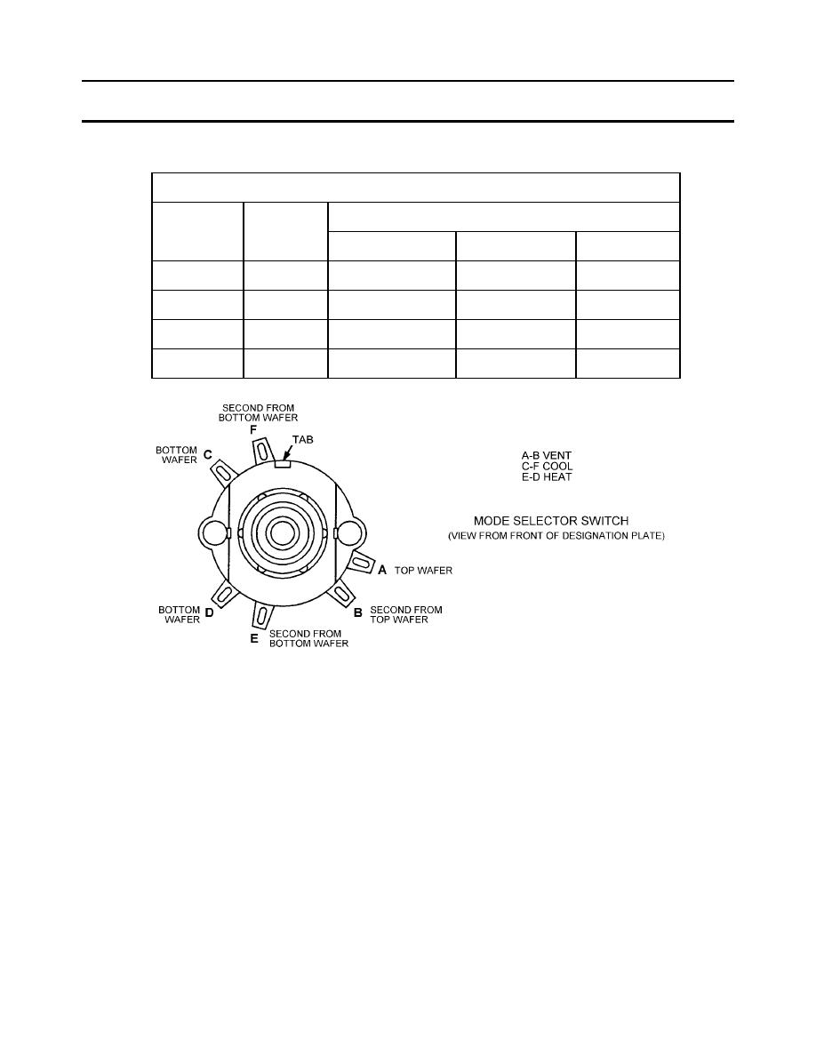
MODE SELECTOR SWITCH
SWITCH SECTION AND TERMINALS CONNECTED
POSITION
FUNCTION
S1A
S1B
S1C
1
OFF
-- -- -- -- -- --
-- -- -- -- -- --
-- -- -- -- -- --
2
VENT
A AND B
-- -- -- -- -- --
-- -- -- -- -- --
3
HEAT
A AND B
E AND D
-- -- -- -- -- --
4
COOL
A AND B
-- -- -- -- -- --
C AND F
Figure 2. Mode Selector Switch
DISASSEMBLY (Refer to Exploded View Figure 3)
NOTE
Disassembly should be limited to the replacement of defective parts.
1.
Loosen setscrew on knob (3) and remove knob from mode selector switch (12).
2.
Loosen setscrew on knob (4) and remove knob from potentiometer (15).
3.
Remove four screws (5), four flat washers (7), and four lock washers (6), to open control box (9) and control panel
(8). Be careful of the wiring.
4.
Remove mode selector switch (12) and potentiometer (15) from control panel (8) by removing nuts (10) and (13)
and lockwashers (11) and (14).
5.
If to be replaced after inspection and test, tag and disconnect wires (22) from defective mode selector switch (12)
and potentiometer (15).
0034-00-4
|
|
Privacy Statement - Press Release - Copyright Information. - Contact Us |
