 |
|||
|
|
|||
|
|
|||
| ||||||||||
|
|
 TM 9-4120-428-14
0090 00
L1
L3
L2
HR7
B1
GFEDCBA
GFEDCBA
COMPRESSOR
COMPRESSOR
WIRING DIAGRAM
WIRING DIAGRAM
3
5
2
1
2
5
3
1
4
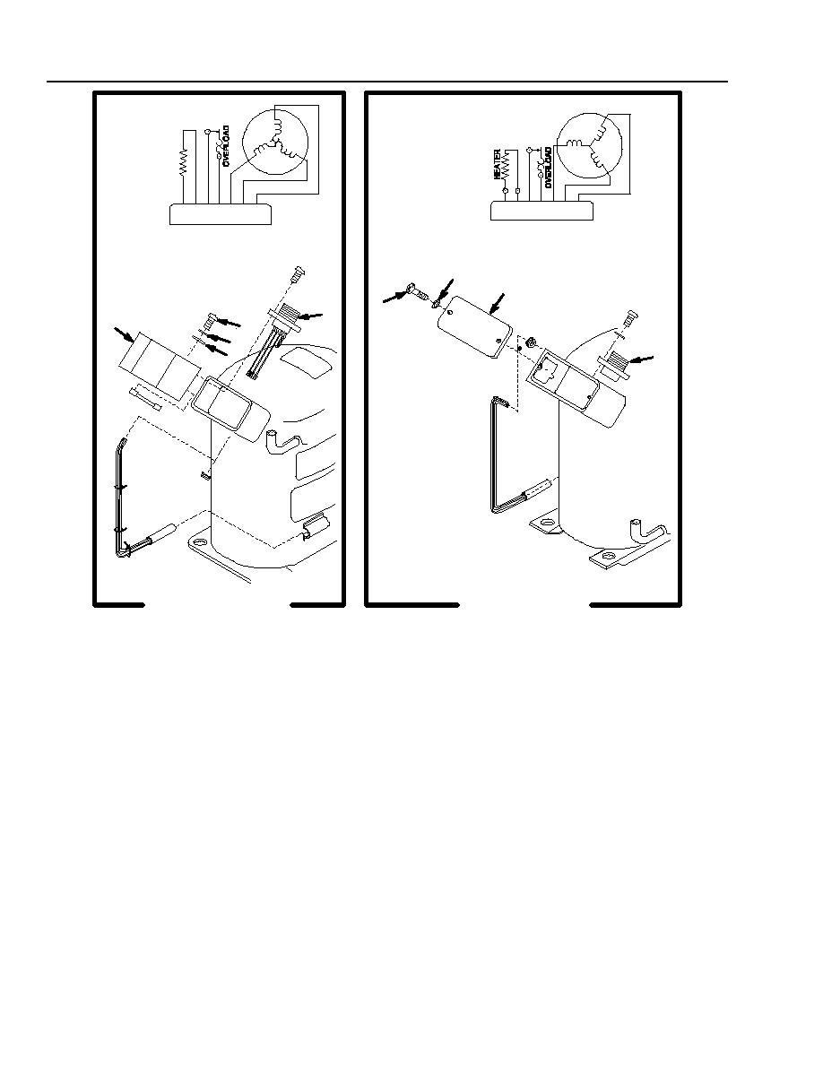
KECO INDUSTRIES 3
WELCO INDUSTRIES
PHASE COMPRESSOR
REPAIR
A. Crankcase Heater (3-Phase Only)
1) Disconnect the heater leads from pins F and G of J10 (Figure 5 -32, Item 1). Pull leads through the grommet
(2).
2) Pull the heater (3) from the mounting clip.
3) Place the new heater (3) in the mounting clip.
4) Run the heater wires through the grommet (2).
5) Connect the heater leads to J10, pins F and G.
6) Secure the heater wires with tie down straps.
B. Connector (J10)
1) Remove four screws (9), lock washers (10 WELCO Only), nut plate (11 KECO Only).
2) Tag and unsolder all wire leads.
3) See the Wiring Diagram. Solder all leads to the new connector and remove tags.
4) Secure the connector (1) with four screws (9), lock washers (10 WELCO Only), and nut plate (11
KECO Only).
0090 00-2
|
|
Privacy Statement - Press Release - Copyright Information. - Contact Us |
