 |
|||
|
|
|||
|
|
|||
| ||||||||||
|
|
 TM 5-4110-217-14
cracks, dents, and broken fins. Replace defective parts.
NOTE
c. Installation.
Do not use a pry to loosen the cylinder
(1) Install new cylinder head gasket (166) on
head It may damage the head or
crankcase.
crankcase A soft-faced hammer may be
(2) Align holes in gasket (166) and cylinder
carefully used to sharply tap the cylinder
head (161) with holes in crankcase with nine bolts (163 &
head edge Take care not to break any
165) and washers (164). Tighten bolts to a torque of 5
cooling fins
foot-pounds; then 1 foot-pounds, etc., until all are
b. Cleaning and Inspection.
torqued to 29 to 31 foot-pounds. Refer to figure 5-15 for
(1) Carefully clean cylinder head, crankcase,
head bolt tightening sequence.
and top of piston with scraper or wire brush. Use
(3) Install spark plug (84) gasket (85) and
approved cleaning solvent to clean all applicable parts.
connect ignition cables (220 and 221).
Dry parts thoroughly.
(2) Inspect all threaded parts for damaged
threads. Inspect cylinder head and crankcase for
.
Section IV. VALVES
revolution and again line up the TC marks. Then follow
5-16. General.
the adjustment given for the valves of the left hand
Positive type valve rotors are furnished in this model
cylinder.
engine The action of the rotor cap, which rotates the
valve slightly each time the valve opens, helps prevent
5-18. Removal of Valves (Figure 3-11).
sticking valves, and will impart a wiping action between
the valve face and valve seat, thereby preventing the
buildup of foreign deposits. Valve rotation will also avoid
If a valve face is burned or warped, or the stem is worn,
prolonged exposure of any one section of the valve face
install a-new valve
to a local hot spot on the seat which will result in lower
a. Remove engine from refrigeration unit (para 3-
and more uniform valve face and seat temperatures.
22).
b. Remove cylinder head (para 5-15).
5-17. Valve Tappet Adjustment.
c. Remove valve tappet cover (para 5-16a).
a. Valve Tappet Inspection Cover Removal (fig. 3-
d. Using valve spring compressor Onan Part No.
11).
420-0119, compress valve spring (172). Remove valve
(1) Remove screw (158) and washer (159) that
spring washer lock (169) from valve stems.
attaches valve tappet inspection cover (157) to
crankcase.
(2) Remove inspection cover and gasket
(160).
b. Adjustment.
(1) Crank the engine over slowly by hand until
the left hand intake valve, when facing the flywheel,
opens and closes. Continue about 1/4 turn until the TC
marks are aligned. This should place the left hand piston
at the top of its compression stroke which is the position
it must be in to get proper valve adjustment for the left
hand cylinder.
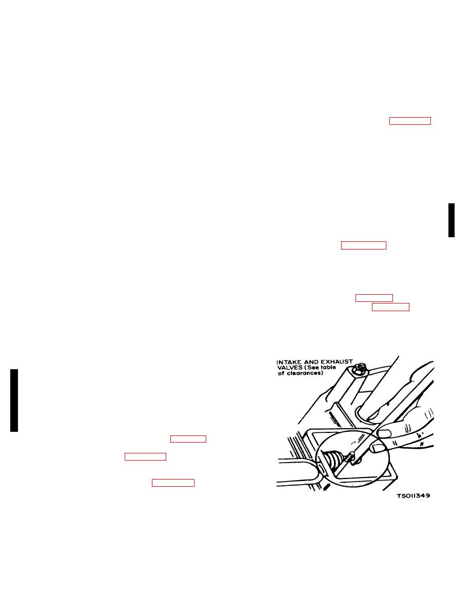
(2) Clearances are indicated in para. 1-5. For
each valve, the gauge should just pass between the
valve stem and valve tappet (figure 5-16).
(3) To correct the valve clearance, turn the
valve adjusting screw as needed to obtain the right
clearance. The screw is self-locking (figure 5-17).
(4) To adjust the valves on the right hand
cylinder, crank the engine over one complete
.
Figure 5-16. Adjusting Tappets (Model RMP-J/1-1OG)
Change 3 5-10
|
|
Privacy Statement - Press Release - Copyright Information. - Contact Us |
