 |
|||
|
|
|||
|
|
|||
| ||||||||||
|
|
 TM 5-4110-217-14
(181) and gear assembly (153-2) remove the
c. Installation
cylinder head (para 5-13) and valve assemblies (para 5-
(1) When pressing a camshaft gear(15b-
14). Remove the operating plunger (107) for the breaker
2)onto the camshaft (181), be sure the gear is started
points (102). Remove the fuel pump (para 3-27) and
straight and that the key (181A) is properly , 1 place.
tappets (168)
Install the governor cup assembly to the g( i before
(3) The camshaft may be pressed out of the
installing the camshaft and gear assembly in the engine
gear (153-2) by use of a hollow tool or pipe which will fit
(2) Each timing gear (153) Is stamped With an
over the camshaft center pin (179). Do not press on the
O mark near the edge The gear teeth of the gear set
center pin or damage it in any way. The governor ball
must mesh so that these marks coincide exactly when
spacer is a press fit to the camshaft gear.
the gears are Installed in the engine (fig 5-13) Be sure,
when installing the camshaft gear (153-2) and shaft
assembly (181) that the thrust washer (154) is properly In
place behind the camshaft gear (153-2) Replace the
plate(156) and lock ring(155)to the crankshaft (199).
(3) Reassemble governor cup, gear cover, and flywheel
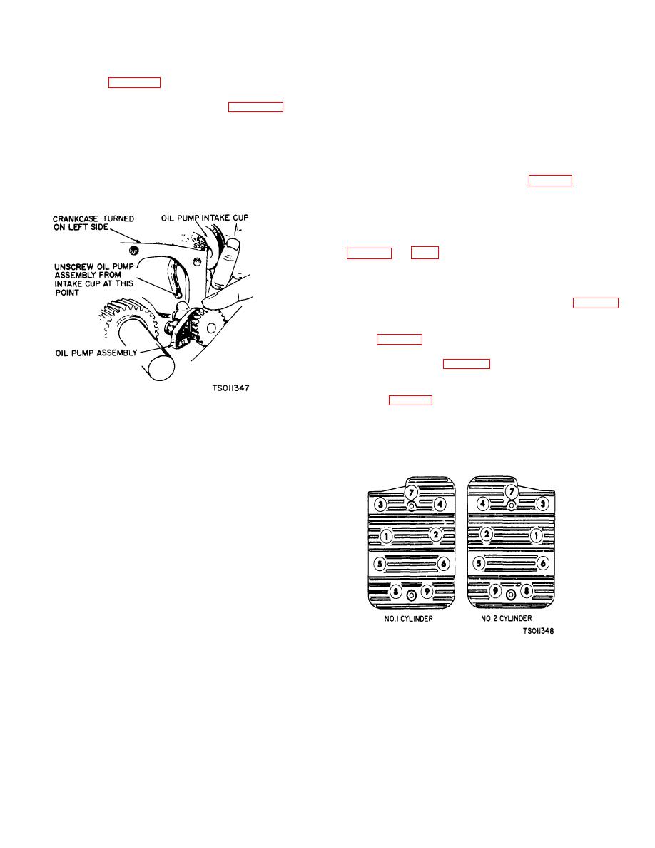
5-13. Oil Pump.
a. Removal.
(1) Remove flywheel and gear cover (para 5-9
& 5-10).
(2) Remove two screws (183) and washers
(184), fig. 3-11, holding pump assembly (182) to engine
and replace complete pump assembly, if worn.
b. Installation (fig. 5-14). Oil the pump to prime it
before reinstalling. Use a new gasket. Replace oil pump
intake cup, if necessary Reinstall gear cover and
flywheel (para 5-9 & 5-10).
Figure 5-14. Oil Pump (Model RMP-J/1-10G).
Section III. CYLINDER HEADS
5-14. General.
The cylinder head forms a removeable, shaped cover for
the combustion chamber.
5-15. Cylinder Head.
CAUTION
Do not remove heads when they
are hot. Warpage may occur.
a. Removal (fig. S-11).
(1) Disconnect ignition cable (220 & 221) from
spark plug (84). Remove spark plug and gasket (85).
(2) Remove nine bolts (163, 165), and
washers (164) that attach cylinder head (161) to
crankcase (162).
(3) Remove cylinder head (161) and gasket
Figure 5-15. Cylinder Head Bolt Tightening Sequence
(166). Discard gasket.
(Model RMP-J/1 -l10G)
5-9
|
|
Privacy Statement - Press Release - Copyright Information. - Contact Us |
