 |
|||
|
|
|||
|
Page Title:
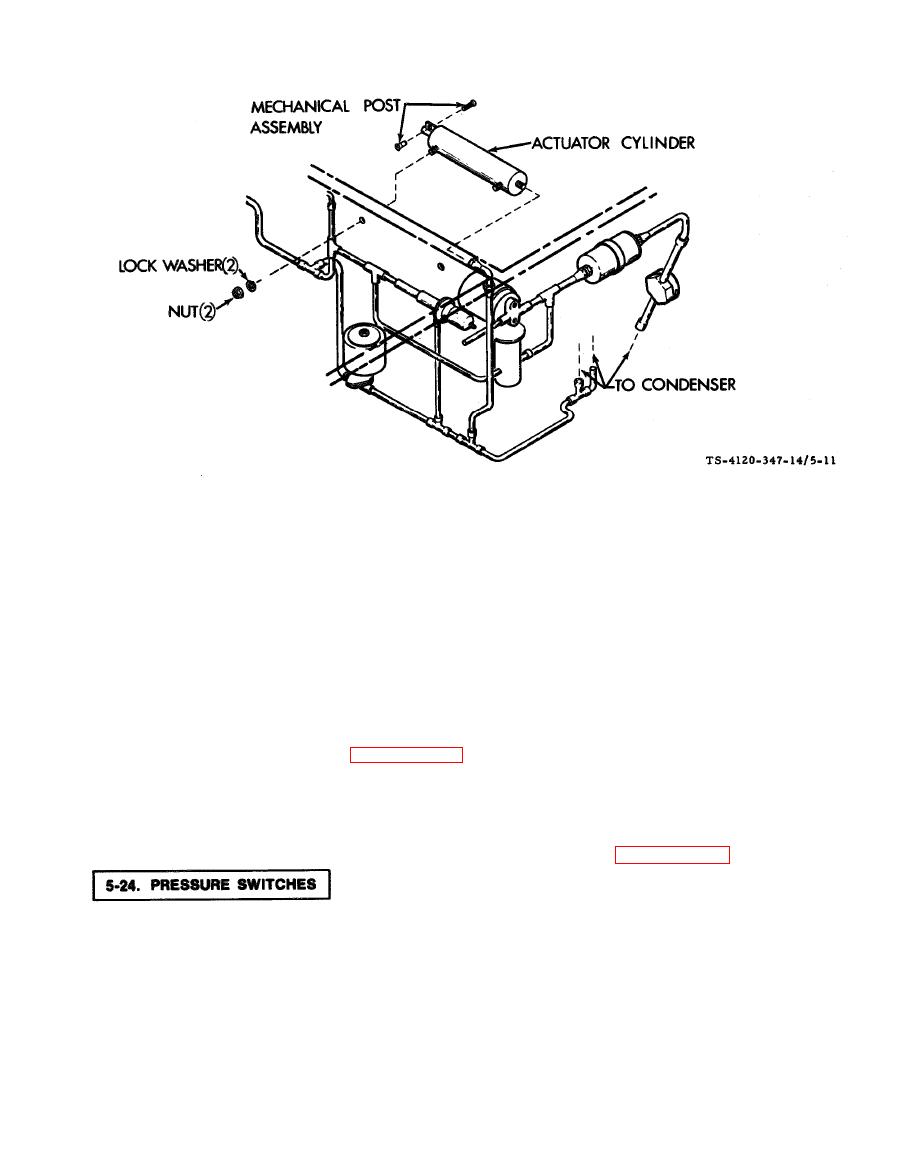
Figure 5-11. Actuating Cylinder |
|
||
| ||||||||||
|
|
 TM5-4129-347-14
b. Installation/Adjustment.
(1) Align the studs on the actuating cylinder with the holes in the bulkhead and secure with two each lock
washers and nuts.
(2)
Connect the swivel elbow flare nut to the actuating cylinder.
Loose assemble the control cable and the mechanical post.
(3)
CIose the condenser discharge air louvers.
(4)
Pull wire from push-pull cable tight and tighten screw in the mechanical post assembly.
(5)
Replace the dehydrator. (See paragraph 5-28.)
(6)
(7)
Leak test the newly connected joints and all connections in the area.
Install the top front and rear covers.
(8)
(9)
Evacuate and charge the refrigeration system in accordance with paragraphs 5-13 and 5-14.
The high pressure switch S4 and low pressure switch S5 are located on the front of the unit below the control
module and junction box.
a. Access.
(1) Disconnect power at the power source.
(2) Remove the control module and junction box. It is not necessary to totally remove all wire connmtlona
and capillary line so long as the junction box can be pulled out enough to gain access to the pressure switches,
Support the junction box so that wires and capillary line is not damaged.
5-27
|
|
Privacy Statement - Press Release - Copyright Information. - Contact Us |
