 |
|||
|
|
|||
|
Page Title:
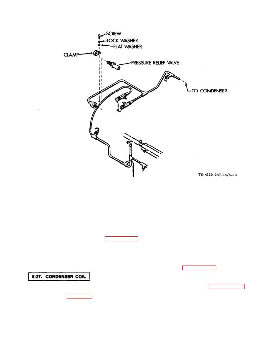
Figure 5-14. Pressure Relief Valve |
|
||
| ||||||||||
|
|
 TM5-4120-347-14
Pressure Relief Valve
b. Installation.
(1) Use two wrenches, one to hold the fitting and the other to tighten the valve. Screw the valve into the
fitting.
(2) Secure the valve with a screw, lock washer, flat washer and clamp.
(3) Replace the dehydrator. (See paragraph 5-28.)
(4) Leak test the newly connected joints and all connections in the area.
(5) Install the top rear cover.
(6) Evacuate and charge the refrigeration system in accordance with paragraphs 5-13 and 5-14.
The condenser coil is located across the rear of the unit. For cleaning instructions see paragraph 4-46.
a. Removal. (See figure 5-15.)
(1) Disconnect power at power source.
(2) Remove the top rear cover.
5-31
|
|
Privacy Statement - Press Release - Copyright Information. - Contact Us |
