
TM 10-8145-222-23
0060
REPLACE CONTINUED
25. Solder small upper refrigerant pipe (Figure 20, Item 1) at solder location (Figure 20, Item 2).
CAUTION
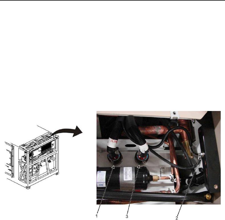
When reconnecting evaporator connectors 1CP and 2CP, make sure to route them in
such a way as to avoid interference with V-belts during operation.
NOTE
The ground wires for connectors 1CP and 2CP are attached to a single shared
ground with a screw and a nut.
26. Reconnect evaporator electrical connector 2CP (Figure 21, Item 3) and green ground wire (Figure 21, Item 2)
as tagged. Remove tag.
27. Reconnect evaporator electrical connector 1CP (Figure 21, Item 1) and green ground wire (Figure 21, Item 2)
as tagged. Remove tag.
Figure 21. 1CP and