 |
|||
|
|
|||
|
|
|||
| ||||||||||
|
|
 TM5-4110-234-14
TO 40R7-5-7-1
(5)
Be sure that the flare nut is tight. Turn the discharge valve stem one turn clockwise to "crack" the valve.
(6)
Using a water and soap solution check the newly connected fittings for leaks.
(7)
Reinstall the protective cap over the valve stem.
(8)
See wiring diagram figures 4-5 or 4-6 and tags and connect wire leads.
(9)
Close the control panel and secure with two screws and lock washers.
(10)
Close access doors and connect power.
4-36. THERMOSTAT
See figures 4-2, 4-3 and 4-21.
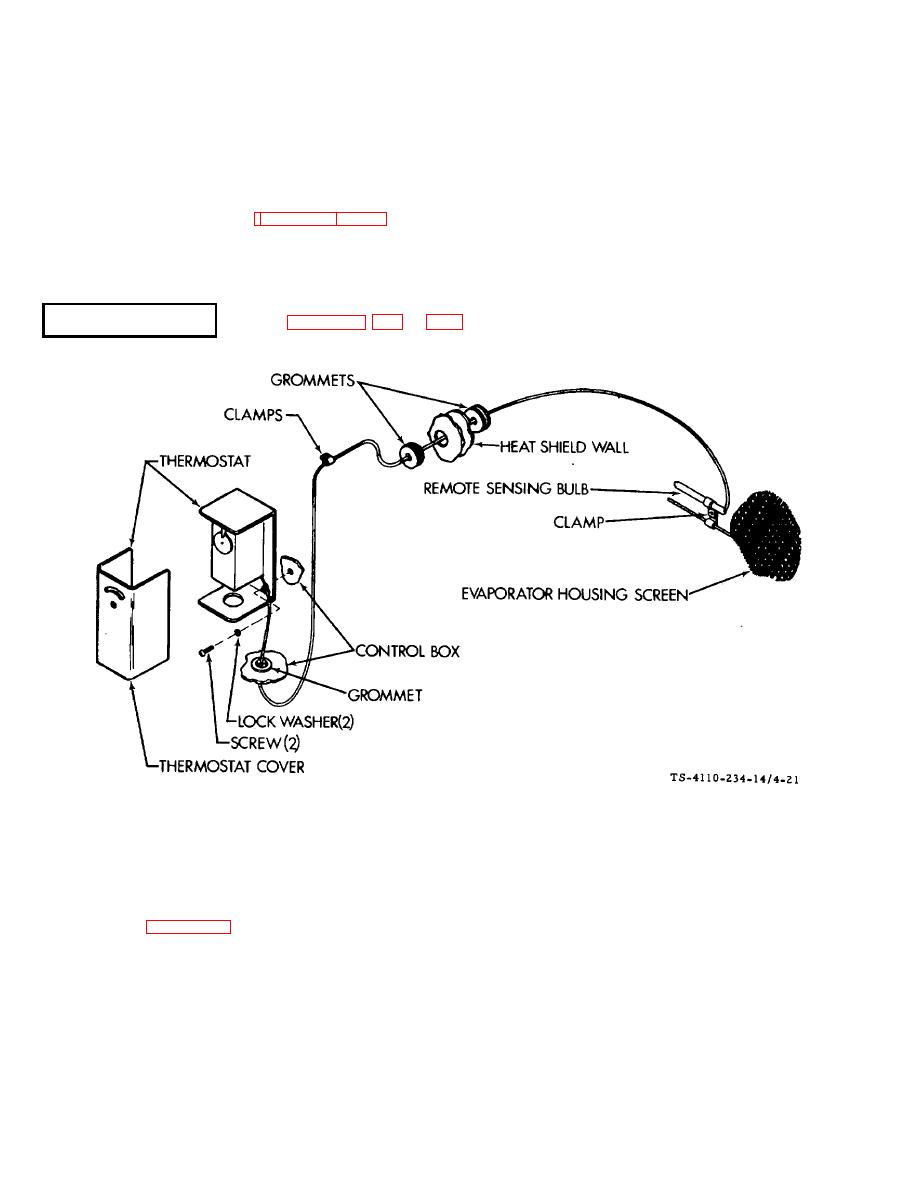
Figure 4-21. Thermostat
a. Removal.
(1)
Disconnect power.
(2)
(3)
Loosen the screw and nut holding the clamp and slip the remote sensing bulb out of the clamp.
(4)
Remove two screws and lock washers and open the control panel door.
(5)
Remove the tube clamps and carefully cut the plastic tie wraps that hold the capillary line in place.
4-48
|
|
Privacy Statement - Press Release - Copyright Information. - Contact Us |
