 |
|||
|
|
|||
|
Page Title:
Figure 5-13. Compressor Pump End Bearing Head |
|
||
| ||||||||||
|
|
 TM5-4110-234-14
TO 40R7-5-7-1
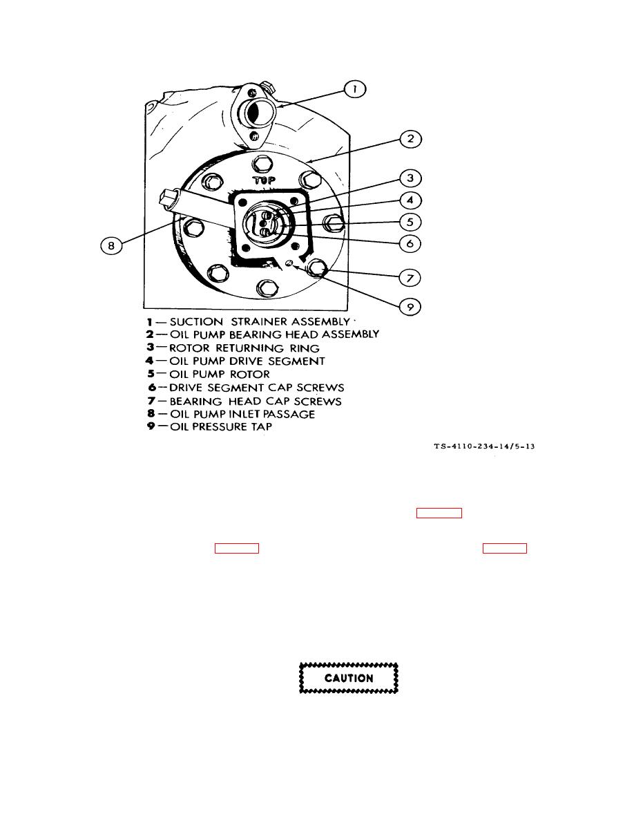
Figure 5-13. Compressor Pump End Bearing Head
d. Replacement/Reassembly.
(1) Bolt the bearing head to the crankcase, using the eight cap screws (7, fig. 5-13). The bolt torque should ' be
25 to 30 ft-lb.
(2) Bolt the drive segment (4, fig. 5-13) to the crankshaft, using the two cap screws (6, fig. 5-13). Bolt torque 4
to 6 ft-lb on the No. 10 screw and 8 to 14 ft-lb on the 1/4 inch screw.
(3)
Insert the oil feed guide vane with the large diameter inward.
NOTE
The guide vane must be installed before the vane spring.
(4)
Place the oil feed vane spring over the small diameter of the guide vane.
Do not over-torque the four cover plate cap screws, since aluminum threads in bearing
head could be stripped.
(5)
Install the cover plate with a bolt torque of 16 to 24 ft-lb.
5-36
|
|
Privacy Statement - Press Release - Copyright Information. - Contact Us |
