 |
|||
|
|
|||
|
|
|||
| ||||||||||
|
|
 TM5-4110-234-14
TO 40R7-5-7-1
5-31.
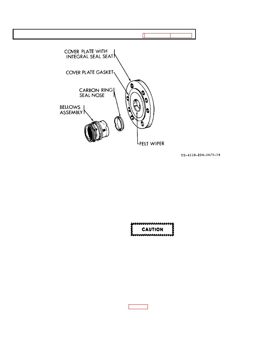
CRANKSHAFT SEAL ASSEMBLY (F10000RG-2) See figures 5-10 and 5-14.
Figure 5-14. Seal Assembly
The crankshaft oil seal is a sleeve type with rotating bellows and integral seal seat.
a.
Disassembly.
(1)
Remove the cap screws and slip the cover plate, gasket and shaft seal from the crankshaft.
(2)
Inspect all parts including crankshaft for obvious wear, broken parts and other visible damage.
b.
Replacement/Reassembly.
Do not attempt to repair or replace seal components. Replace complete seal assembly
with current sleeve type. The bellows assembly of the service replacement seal must not
be taken apart.
(1)
Pump end bearing head must be in place for proper positioning of seal on crankshaft.
(2) Be sure shaft extension, expecially the edges of the keyway, is free of sharp edges and nicks. Also, shaft
must be clean and free of rust. Polish the shaft with crocus cloth.
(3)
Check seal assembly to be sure the bellows are properly in place and are clean.
(4) Lubricate shaft and neoprene bellows (with compressor oil only) where it contacts shaft. Slide seal assembly
onto shaft until neoprene starts to grasp the shaft. (See fig. 5-15.)
5-37
|
|
Privacy Statement - Press Release - Copyright Information. - Contact Us |
