 |
|||
|
|
|||
|
Page Title:
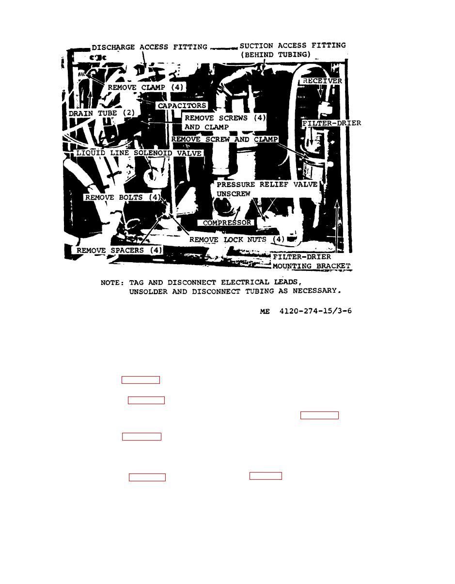
Figure 3-6. Compressor, pressure relief valve, capacitors, liquid line solenoiol valve, remove and installation |
|
||
| ||||||||||
|
|
 TM 5-4120~274-15
remove and installation
3-24. Fan Motor
inlet ring and evaporator fan.
a. General. The fan motor in the CV-9 series
air conditioner drives both the evaporator and
c. Installation. Refer to figure 37, and install
condenser fans.
inlet ring and evaporator fan.
motor.
c. lnspection and Testing.
(1) Inspect for dents, cracks and broken or
condenser fan.
damaged leads.
b. Inspection. Inspect unit for dents, cracks,
(2) Test for continuity across windings with
bends and chipped paint.
a multimeter set on OHMS. Refer to the wiring
diagram figure 1-5 to establish points for continu-
ity.
condenser fan.
|
|
Privacy Statement - Press Release - Copyright Information. - Contact Us |
