 |
|||
|
|
|||
|
Page Title:
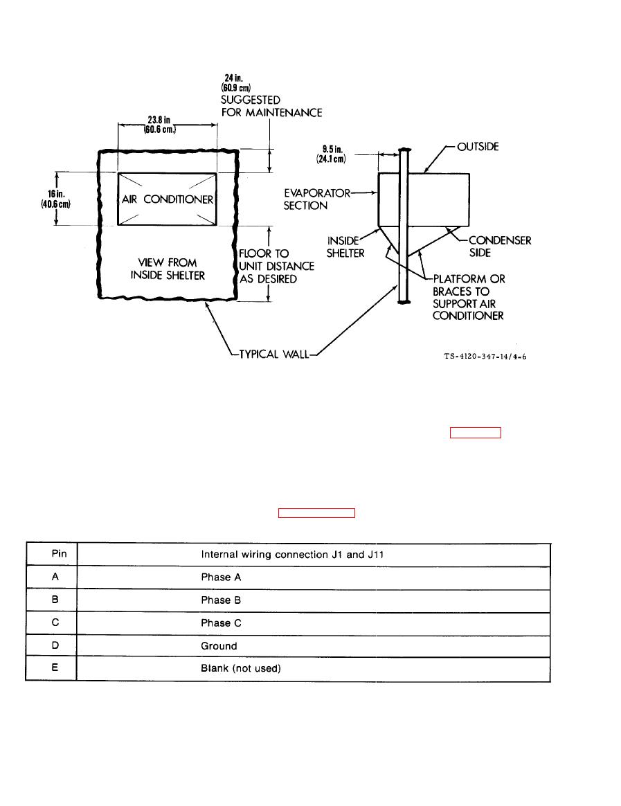
Figure 4-6. Typical Through the Wall Installation |
|
||
| ||||||||||
|
|
 TM5-4120-347-14
d. Connect a 10 AWG ground wire from the shelter ground to the air conditioner external ground. The air
conditioner external ground is located on the front face to the left of the control module. See figure 1-2, item 18.
e. Fill in and seal the area around the air conditioner to prevent the loss of conditioned air. Flexible plastic
foam and pressure sensitive tape may be used,
f. Fabricate an input power cable of the required length using the MS3106R18-11S connector supplied with
the air conditioner for connection to the J1 or J11. If the J11 connector is used, be sure the wiring tothe TB3 and
TB4 terminal boards is relocated in accordance with paragraph 4-6.
g. Remove the condensate drain plug from the lower left rear corner of the unit. If the air conditioner is
mounted in a location where water pouring from this drain will be objectionable or create a hazard, connect a
drain line at this point. The fitting used must have a male 1/8 -- 27 NPT connection to the unit. Hose, rigid pipe
or tubing can be used to direct the drain water to a more desirable disposal location.
4-14
|
|
Privacy Statement - Press Release - Copyright Information. - Contact Us |
