 |
|||
|
|
|||
|
Page Title:
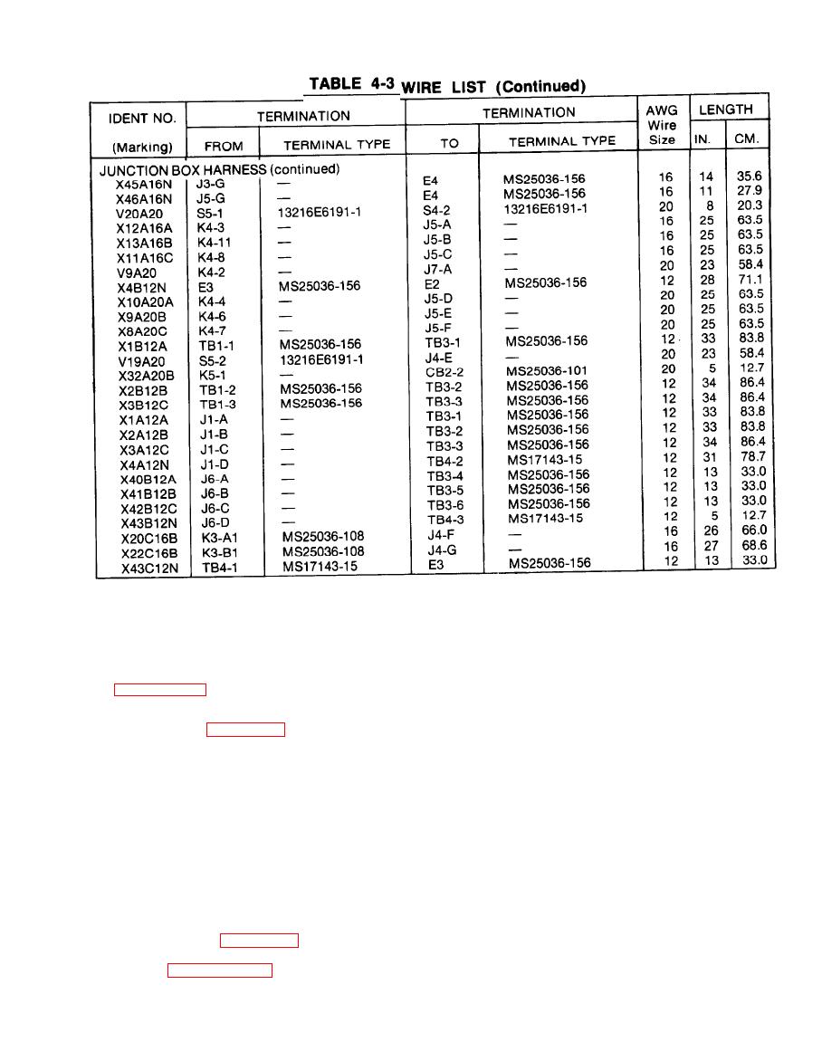
TABLE 4-3 WIRE LIST - continued |
|
||
| ||||||||||
|
|
 TM5-4120-347-14
The control module is normally located in the upper left front corner of the unit, H can be remote mounted
(see paragraph 4-6c).
a. Removal. (See figure 4-18.)
(1) Disconnect power at power source.
(2) Remove the return air louver,
(3) Loosen the sensing bulb clamp screws and slip the sensing bulb out of the clamps.
(4) Loosen the control module mounting screw and carefully pull the control module out of the unit. Use
care to avoid damage to the sensing line.
(5) Carefully work the sensing bulb through the frame and out of the unit.
b. Test/Repair (See figure 4-19.)
(1) See paragraphs 4-28 through 4-32 for testing of individual components.
4-43
|
|
Privacy Statement - Press Release - Copyright Information. - Contact Us |
