 |
|||
|
|
|||
|
Page Title:
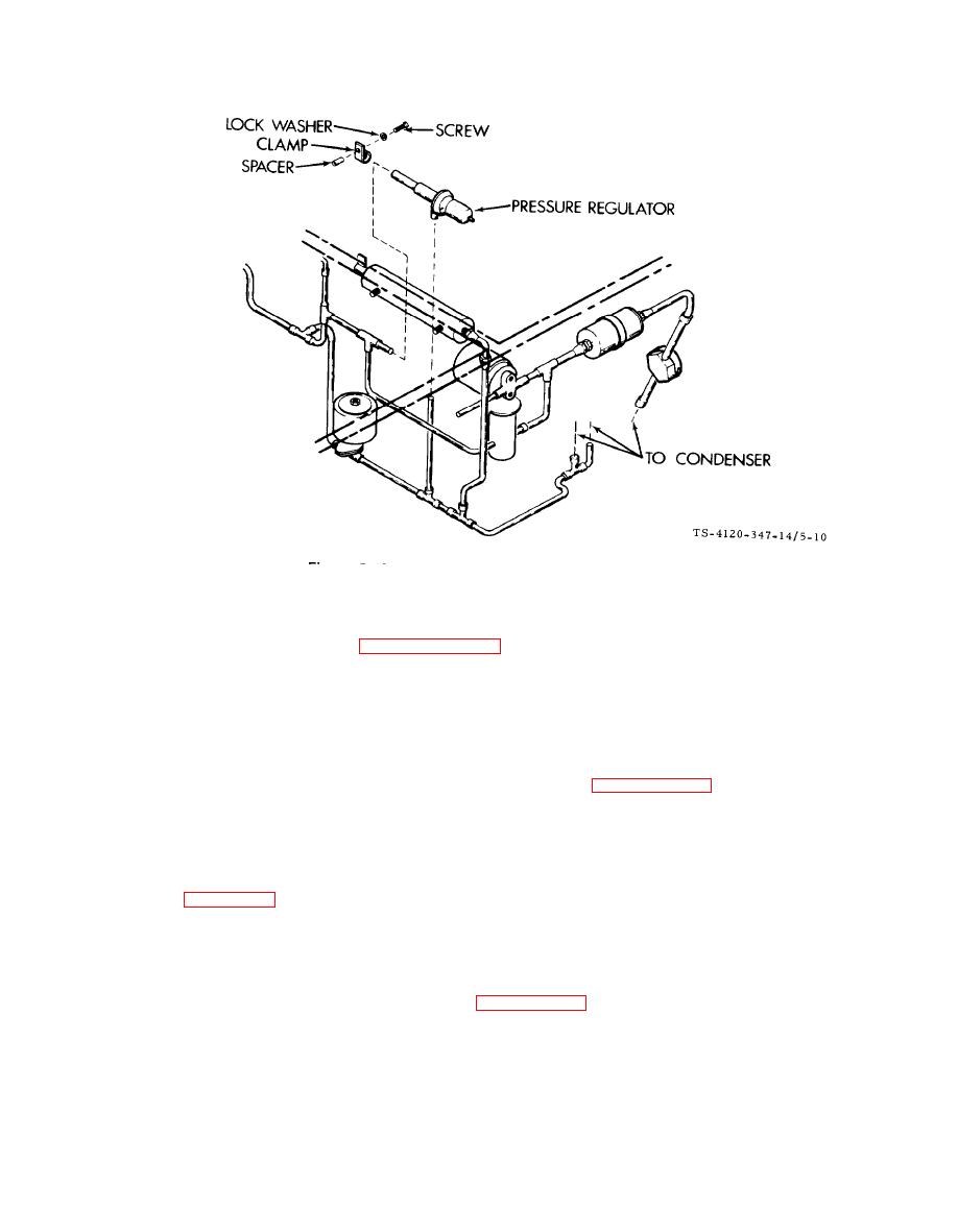
Figure 5-10. Pressure Regulator |
|
||
| ||||||||||
|
|
 TM5-4120-347-14
F i g u r e 5-10. Pressure Regulator
R e p l a c e the dehydrator, (See paragraph 5-28.)
(4)
Leak test the newly connected joints and all connections in the area.
(5)
Secure the pressure regulator with a screw, lock washer clamp and post spacer.
(6)
Install the top front and rear covers.
(7)
(8)
Evacuate and charge the refrigeration system in accordance with paragraphs 5-13 and 5-14.
The actuating cylinder is located in the rear (compressor/condenser) compartment.
a. Removal. See figure 5-11.
(1) Disconnect power at the power source.
(2) Remove the top front and rear covers.
(3) Discharge and purge the refrigeration system per paragraphs 5-9 and 5-10.
(4) Remove the screw from the mechanical post assembly and slip the push-pull cable wire loose. Take
care not to lose the mechanical post,
(5)
Disconnect the actuator cylinder from the flare nut on the elbow.
(6)
Remove the two nuts and lock washers and slip the actuator cylinder out of the unit.
5-26
|
|
Privacy Statement - Press Release - Copyright Information. - Contact Us |
