 |
|||
|
|
|||
|
Page Title:
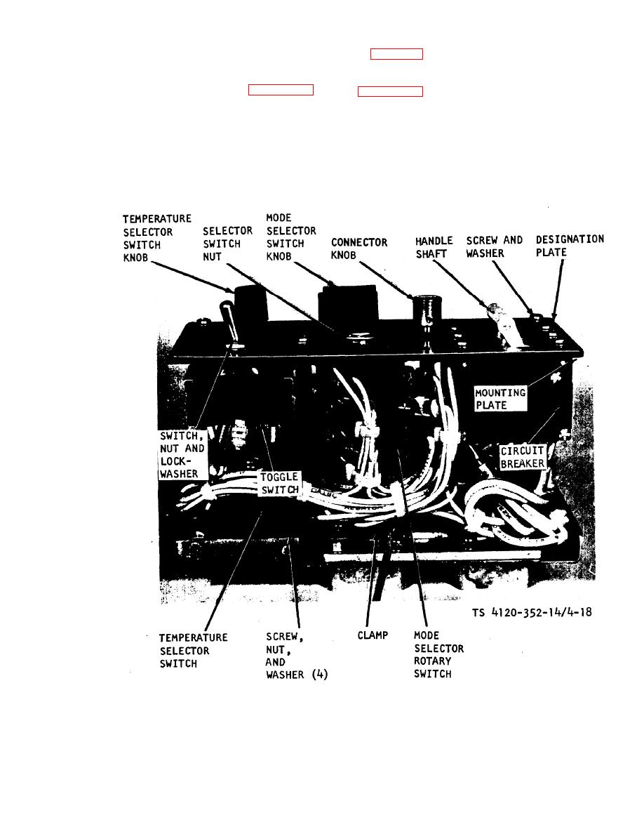
Figure 4-17. Control module less cover. |
|
||
| ||||||||||
|
|
 TM 5-4120-352-14
placement of individual controls. Remove control
to figure 4-17 and remove the switch nut and lock-
module cover and mark and disconnect leads of con-
washer, Remove toggle switch.
trol to be replaced.
(4) Temperature Selector Switch. Refer to
remove handle shaft and spacers. Remove six
clamp, Remove four screws, nuts, and washers. Re-
screws and washers that secure circuit breaker to
move switch knob and temperature selector switch.
mounting plate and designation plate and remove
(5) Mode Selector Rotary Switch. Refer to
circuit breaker.
switch 4-17, loosen setscrew in knob and remove
(3) Evaporator Fan Toggle Switch. Refer
knob. Remove switch nut and switch.
Figure 4-17. Control module less cover.
4-35
|
|
Privacy Statement - Press Release - Copyright Information. - Contact Us |
