 |
|||
|
|
|||
|
Page Title:
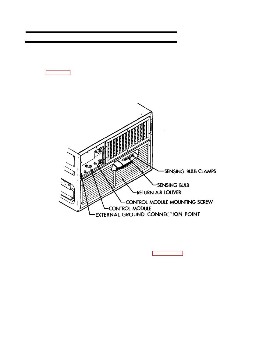
Figure 4-3. Control Module Removal |
|
||
| ||||||||||
|
|
 TM5-4120-383-14
4-4.
INSTALLATION
INSTRUCTIONS.-Continued
(2) Connectors are provided to permit remote installation of
the control module.
If it is determined that it is desirable to
mount the control module in a remote (mounted elsewhere in the
conditioned space) location the following steps must be taken.
(See fig. 4-3.)
Control Module Removal
Remove return air louver (para 4-13).
(a)
(b) Loosen sensing bulb clamp screws and slip sensing bulb
out of clamps.
(c) Loosen control module mounting screw and carefully pull
control module out of unit. Use care to avoid damage to sensing
line.
(d) Carefully work sensing bulb through frame and out of
the unit.
|
|
Privacy Statement - Press Release - Copyright Information. - Contact Us |
