Order this information in Print

Order this information on CD-ROM

Download in PDF Format


Click here to make tpub.com your Home Page

Page Title: Figure 4-23. Lower Panel
Back | Up | Next

Click here for a printable version

Google


Web
www.tpub.com

Home


Information Categories
.... Administration
Advancement
Aerographer
Automotive
Aviation
Combat
Construction
Diving
Draftsman
Engineering
Electronics
Food and Cooking
Math
Medical
Music
Nuclear Fundamentals
Photography
Religion
USMC
   
Products
  Educational CD-ROM's
Printed Manuals
Downloadable Books


TM5-4120-387-14 
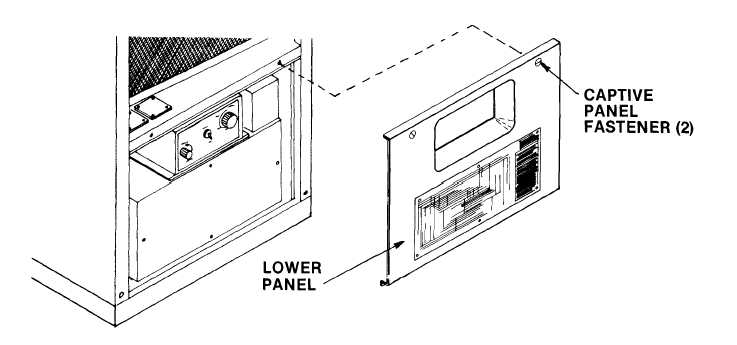
Preliminary procedure: Remove lower panel. (See para 4-24.) a. Removal (1) Place circuit. breaker actuator arm in up position. Figure 4-23. Lower Panel (2) Using screwdriver,    unscrew four panel mounting screws from flanges of casing. (3) Carefully slide junction box outward. (4) Using screwdriver, loosen screws in lower end fitting of circuit breaker control cable. (5) Using screwdriver,    remove two screws from loop clamp. (6) Slide actuator cable up and out. (7) Extend junction box out far enough to remove plugs P4, P8 and P1O. (8) Using screwdriver,    remove four screws at flanges of control panel. (9) Support control panel so that capillary line and electrical harness will not be damaged. 4-71

Privacy Statement - Press Release - Copyright Information. - Contact Us - Support Integrated Publishing

Integrated Publishing, Inc. - A (SDVOSB) Service Disabled Veteran Owned Small Business