 |
|||
|
|
|||
|
|
|||
| ||||||||||
|
|
 TM9-4120-423-14&P
TESTING
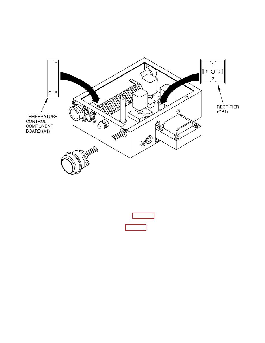
Temperature Control Component Board (A1) Test
1
Evaporator section electrical module assembly must be connected to an operable air conditioner
and remote control assembly.
2
208V, 3 phase, 400 Hz power, and power cable must be available.
3
Top evaporator cover must be removed. (See WP0026.)
4
Top module cover must be removed. (See WP0041.)
WARNING
AC power tests must be conducted with the power on. Exercise extreme caution.
5
Connect power to air conditioner.
6
Turn selector switch to COOL.
7
Turn temperature control to maximum COOLER.
8
Using multimeter, check temperature control output voltage between terminals CR1-4 neg (-)
and A1K1-2. Voltage should be 25 to 31 Vdc.
0035 00-4
|
|
Privacy Statement - Press Release - Copyright Information. - Contact Us |
