 |
|||
|
|
|||
|
Page Title:
TIME DELAY RELAY (K1) TESTING, INSPECTION, REMOVAL, REPLACEMENT, AND INSTALLATION |
|
||
| ||||||||||
|
|
 TM 9-4120-428-14
UNIT MAINTENANCE
AIR CONDITIONER, HORIZONTAL, COMPACT
(NSN 4120-01-502-1319)
TIME DELAY RELAY (K1) TESTING, INSPECTION, REMOVAL, REPLACEMENT, AND INSTALLATION
INITIAL SETUP:
Tools
Materials/Parts
Refrigeration Unit Service Tool Kit, WP 0000 00, Item
Time delay relay
1
self-locking nuts (2)
Power Supply, WP 0000 00, Item 6
Equipment Condition
Remove Junction Box (WP 0036 00)
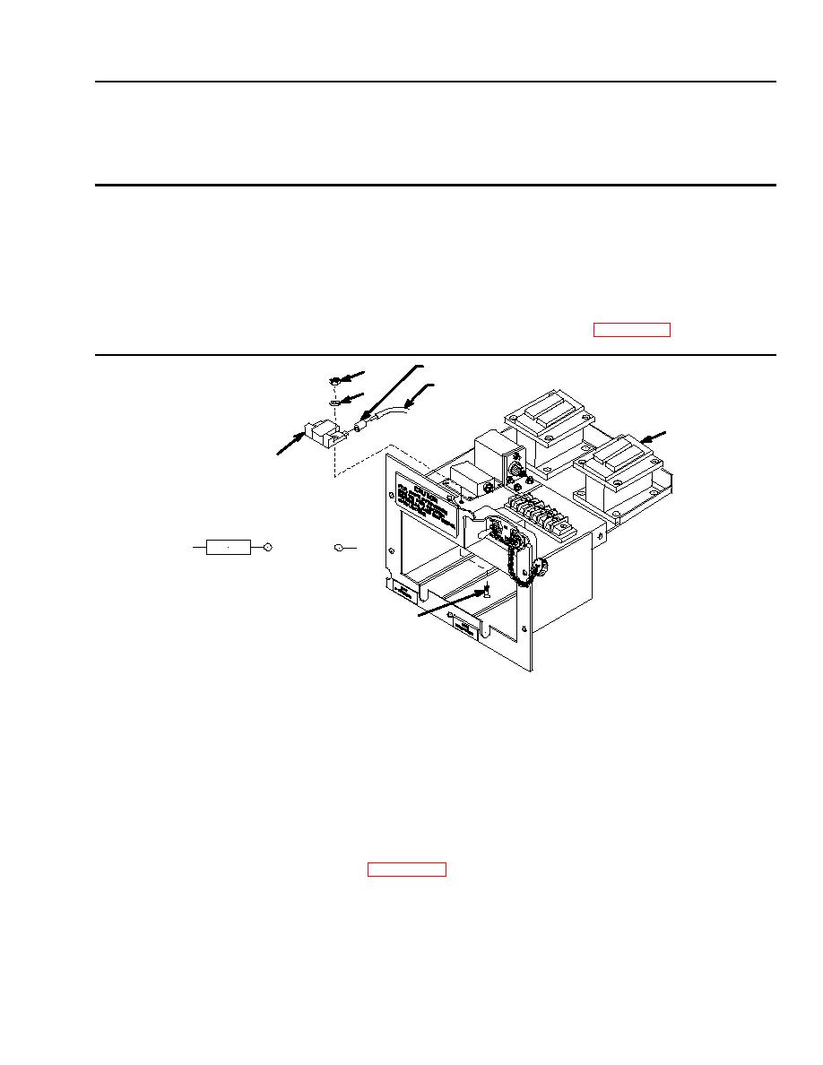
INSULATION (REF)
2
WIRE (REF)
3
K3
4
1
2
-
+
INPUT
RELAY DIAGRAM
1
TESTING
1. Connect the multimeter to terminal A1 and A2 of the relay K3.
2. Apply +28VDC to terminal 6 of TB1 and 28VDC to terminal X2 of K3.
3. Multimeter must show continuity across terminals A1 and A2 within 30 +/- 3 seconds after applying the 28 VDC.
4. Remove the 28 VDC. The multimeter must show that the contacts are open.
INSPECTION
Check relay for general condition and loose, broken, or missing terminals.
REMOVAL
1. Tag and disconnect all wires to the relay. (WP 0038 00).
2. Remove two screws (1), self-locking nuts (2), and flat washers (3).
3. Pull the relay (4) from the junction box.
REPLACEMENT
Replace individual relays if defective.
INSTALLATION
0038 00-1
|
|
Privacy Statement - Press Release - Copyright Information. - Contact Us |
