 |
|||
|
|
|||
|
Page Title:
Figure 1. Temperature Selector Switch Electronic Probe |
|
||
| ||||||||||
|
|
 TM 9-4120-430-14
0028 00
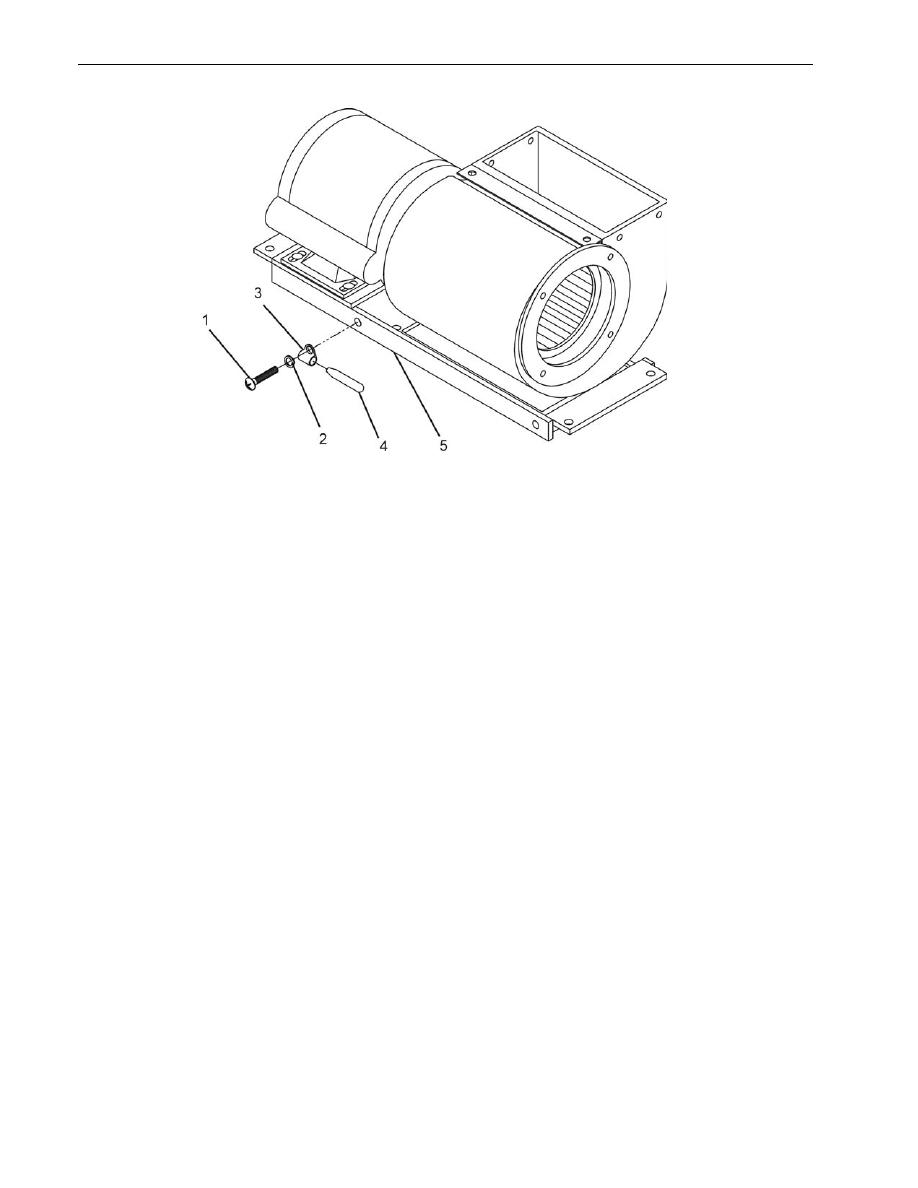
Figure 1. Temperature Selector Switch Electronic Probe
Temperature Selector Switch Electronic Probe (Figure 1)
1.
Loosen screw (1) and washer (2) to release electronic probe (4) from clamp (3) on evaporator fan assembly (5).
2.
Carefully slide out probe (4) from clamp (3).
Junction Box and Lower Housing Plate (Figure 2)
1.
Inspect junction box for damage.
2.
Remove seven screws (1) that secure the junction box (2) to the unit housing.
3.
Remove five screws (3) to remove the lower housing plate (4) from the unit housing.
4.
Partially remove the junction box by pulling it forward and out of the air conditioner. Care must be taken with the
wiring.
5.
Support the junction box to relieve strain on wiring.
NOTE
It is not necessary to remove junction box completely from unit. Most repairs and
replacements can be made without removing junction box completely. Junction box
can be moved out approximately 18 inches from the unit.
6.
Inspect wiring for cracked or frayed insulation and loose connections.
7.
Replace junction box if damaged enough to prevent normal operation of air conditioner.
0028 00-2
|
|
Privacy Statement - Press Release - Copyright Information. - Contact Us |
