 |
|||
|
|
|||
|
Page Title:
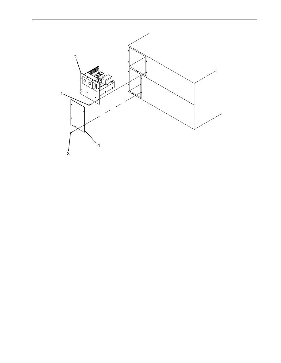
Figure 2. Junction Box and Lower Housing Plate |
|
||
| ||||||||||
|
|
 TM 9-4120-430-14
0028 00
Figure 2. Junction Box and Lower Housing Plate
Compressor Motor and Condenser Motors Relay (K1), Heater Element Relays (K3, K4, and K5),
Evaporator Fan Motor Relay (K2), Time Delay Device (TD) (Figure 3)
1.
Inspect relays for any external damage to housing.
2.
If damaged enough to prevent normal operation of relay, replace relay.
Terminal Boards (TB1 and TB2) and Marker Strips
1.
Inspect terminal boards for dents, breaks, nicks or damaged terminals.
2.
If unrepairable, replace terminal board.
3.
Inspect marker strips for illegibility or damage.
4.
Replace marker strip if damaged.
Connectors J1 and J3
1. Inspect wiring for breaks, fraying, discoloration, or damage. Replace if found.
2. Inspect soldered connections for breaks or damage. Repair or replace if found.
3. Inspect pins for bending or corrosion. Straighten bent pins if possible. Clean minor corrosion. Replace if necessary.
4. Inspect electrical contacts for corrosion. Replace or clean as necessary.
0028 00-3
|
|
Privacy Statement - Press Release - Copyright Information. - Contact Us |
