 |
|||
|
|
|||
|
Page Title:
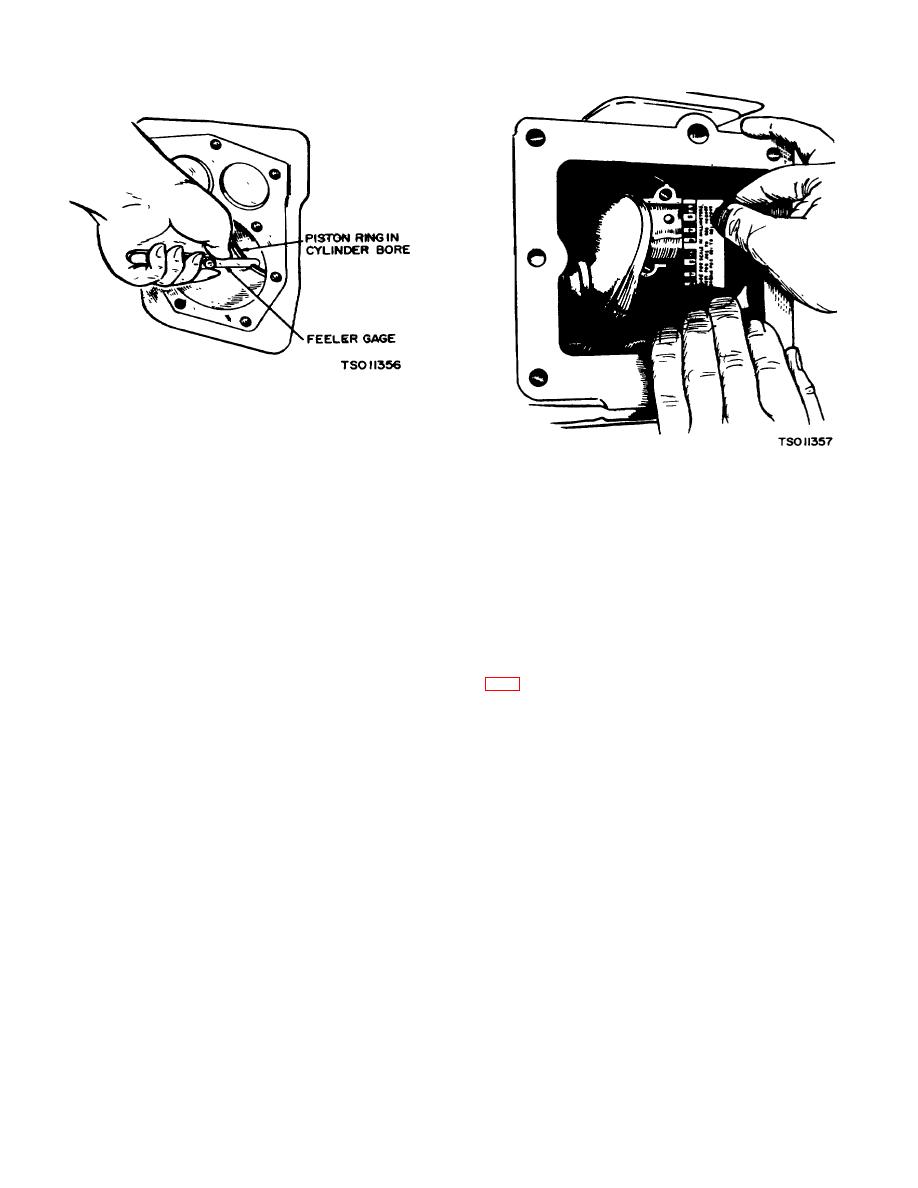
Figure 5-23. Fitting Piston Rings to Cylinder (Model RMP-J/1-10oG) |
|
||
| ||||||||||
|
|
 TM 5-4110-217-14
Figure 5-23. Fitting Piston Rings to Cylinder (Model
RMP-J/1-10oG)
Figure 5-24. Measuring Bearing Clearance with
(4) Install the piston rings (207). Space each
Plastigauge (Model RMP-J/1-1OG)
ring gap one third of the way around the piston from the
preceding one, with no gap directly in line with the piston
caps facing toward the oil base. The rod and cap
pin. The bottom piston ring groove should be fitted with
numbered 2 fits on the crankshaft journal nearest the
an expander and an oil control ring and the two upper
bearing plate.
grooves fitted with compression rings. If a chrome faced
(4) Coat the crankshaft journal bearing
ring is used, it will be in the top groove. The oil control
surfaces with oil before installing the rods.
ring is selected for best performance in regard to the
(5) If necessary, rap the connecting rod cap
correct unit pressure characteristics.
screws (196) sharply with a soft-faced hammer to set the
rod square on the journal.
CAUTION
f. Checking Bearing Clearance With Plastigauge (Fig.
Be careful not to distort rings. Install
rings, gap end first, in piston grooves.
(1) Place a piece of correct size plastigauge in the
Staggering piston ring gaps reduces
bearing cap the full width of the bearing insert about 1/4
engine oil consumption.
inch off center.
(2) Rotate the crank about 30 degrees from bottom dead
e. Installation.
center and reinstall the bearing cap.
(1) Assemble ring compressor tool Onan part
Tighten the connecting rod screw (196) to the torque of
no. 420-0214 over piston rings.
27-29 pounds-foot. Do not turn the crankshaft.
(2) Install the piston and connecting rod
(3) Remove the bearing cap. Leave the flattened d
assembly in cylinder. Back off compression ring tool
plastigauge on the part to which it has adhered and
from piston as each ring enters crankcase.
compare the widest point with the graduations on the
(3) Install the connecting rods (197) and caps
plastigauge envelop to determine bearing clearance.
with raised lines (witness marks) aligned and with the
.
5-14
|
|
Privacy Statement - Press Release - Copyright Information. - Contact Us |
