 |
|||
|
|
|||
|
|
|||
| ||||||||||
|
|
 TM 5-4120-273-15
with a reddish tip; or the flame may be entirely
extinguished.
(2) Soap solution method. Operate the air
conditioner (para 2-12). Brush all points of possi-
ble leakage with soap solution. Watch for bubbles.
Follow a definite sequence so that all joints will
be thoroughly tested. Wipe the solution from all
joints and mark any spot where leakage occurs.
3-6) is automatically actuated by the thermostat
and controls the flow of refrigerant to the evapo-
rator coil.
b. Inspection. Inspect for cracked or broken
casing and damaged or broken terminals.
multimeter set on OHMS. Refer to wiring diagram
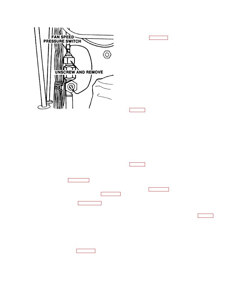
NOTE: TAG AND DISCONNECT
ELECTRICAL LEADS,
UNSOLDER AND DISCONNECT
TUBING AS NECESSARY.
tuated by the ON/OFF switch and serves to equal-
ize system pressures during shutdown, figures
MEC 4120-273-15/3-15
3-11,3-12.
b. Inspection. Inspect for cracked or broken
casing and damaged or broken terminals.
installation.
multimeter set on OHMS. Refer to wiring diagram
a. General. The electric heater thermostat (fig.
3-11) is a protective device which prevents the
3-48. Access Fittings
heater elements from overheating.
a. General. The two access fittings (suction line
move electrical heater thermostat.
and discharge line) provide access to the refriger-
c. Testing. Test for continuity with multimeter
ant system figure 3-6.
set on OHMS. Refer to wiring diagram figure 1-5
b. Inspection. Inspect for cracked casing or
to establish points of continuity.
damaged threads.
install electric heater thermostat.
located on a tee just below the filter-drier. The
a. Inspection. Inspect refrigerant piping for
pressure relief valve protects the refrigerant sys-
kinking, holes and unsatisfactory welding.
tem from excessive pressure.
b. Testing.
b. Inspection. Inspect for cracked or broken
(1) Halide torch leak detector. The pre-
casing.
ferred method of field testing for leaks in the re-
frigeration system is by using a halide torch, Op-
crate the air conditioner (para 2-12) and pass the
The evaporator pressure regulating valve (figs.
exploring tube slowly over all sweat fittings,
mechanical couplings, and valves. If refrigerant is
3-11, 3-12) regulate refrigerant pressure in the
leaking from the system the flame of the torch will
evaporator to prevent coil freeze up. The valve is
change from blue to green when the leak is small.
preset to establish a minimum pressure in the
evaporator of 58 psig.
If the leak is large, the flame will be a deep blue
|
|
Privacy Statement - Press Release - Copyright Information. - Contact Us |
