 |
|||
|
|
|||
|
Page Title:
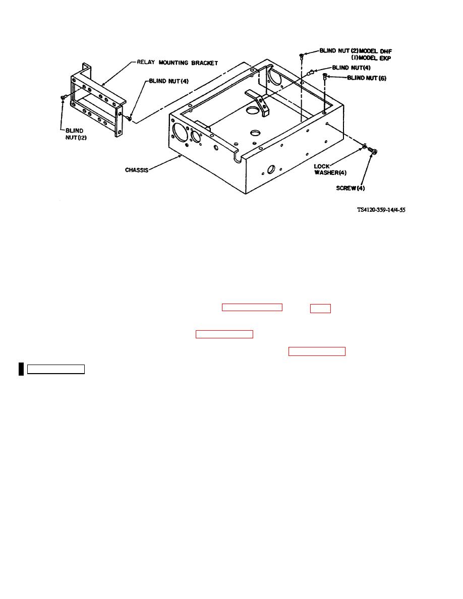
Figure 4-55. Chassis, Evaporator Electrical Module |
|
||
| ||||||||||
|
|
 TM 5-4120-359-14
Figure 4-55. Chassis, Evaporator Electrical Module
(2) Remove component(s) from area to be repaired.
(3) Blind nuts may be removed by drilling them out using a drill bit slightly smaller than the body diameter of the
blind nut. A new one must then be installed.
c.
Replacement/Disassembly/Reassembly
Should it become necessary to replace the chassis, see paragraphs 4-43 through 4-54, for removal and installation of
internal components.
Follow-on Procedures: 1. Install top over. (See paragraph 4-42.)
2. Install evaporator section electrical module. (See paragraph 4-41.)
4-56. DELETED
4-118 Change 6
|
|
Privacy Statement - Press Release - Copyright Information. - Contact Us |
|
|
Integrated Publishing, Inc. - A (SDVOSB) Service Disabled Veteran Owned Small Business
|

