 |
|||
|
|
|||
|
Page Title:
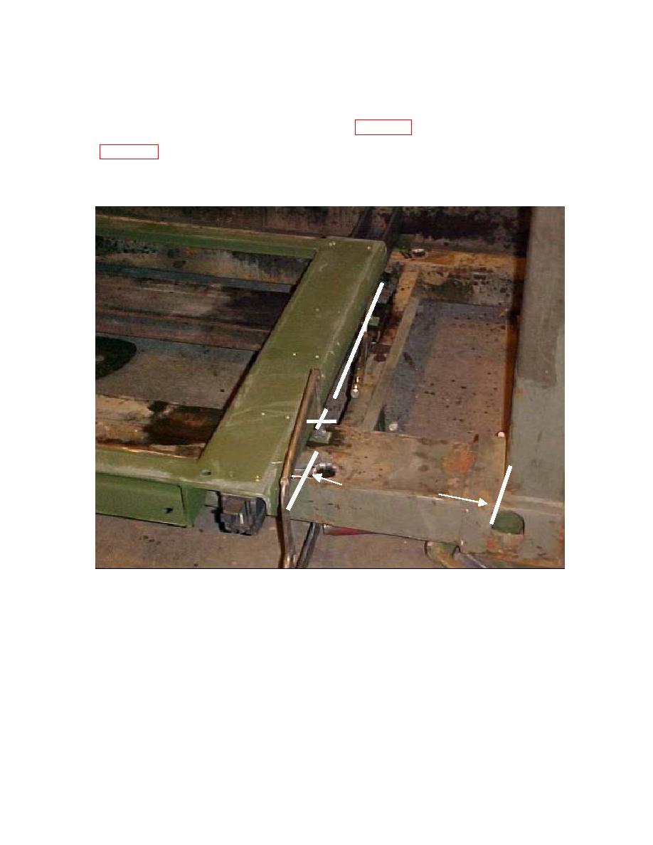
Figure 13A above (slide partially pulled out) and 13B (next page) |
|
||
| ||||||||||
|
|
 MWO 55-8115-202-40-1
(16) Secure the mount assembly in place with clamps (Figure 13A) and locate the six (6) outside
holes by using a center punch or a 9/32" bit. Drill only into metal enough to mark/start hole
mount fully inward so that slides lock and mark these two hole locations onto the container base.
These are holes for the rivet nuts into which the mount locking bolts will fasten during travel.
12 7/16" 1/16"
Critical
Figure 13A above (slide partially pulled out) and 13B (next page)
25
|
|
Privacy Statement - Press Release - Copyright Information. - Contact Us |
