
TM 10-8145-222-23
0078
REPAIR CONTINUED
21. Verify that the FAULT light on the refrigeration unit control display (Figure 10, item 2) illuminates and that the
microprocessor controller display reads CNF1 TV.
22. Carefully remove the insulated jumper wire The configuration screen will now remain available for five minutes.
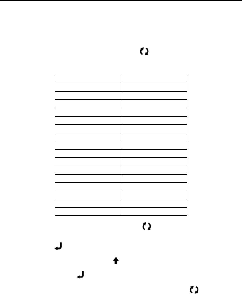
23. Scroll through the configurations list using the FUNCTION
key verifying that the settings match that in
Table 1. If any of the configurations need to be changed continue with step 26 below.
Table 1. Microprocessor Configuration Settings
Function
Setting
CNF1
TV
CNF2
ON
CNF3
OFF
CNF4
OFF
CNF5
ON
CNF6
ON
CNF7
OFF
CNF8
ON
CNF9
OFF
CNF10
OFF
CNF11
OFF
CNF12
OFF
CNF13
OFF
CNF14
OFF
CNF15
OFF
CNF16
OFF
24. To change the configuration selection, press the FUNCTION
key to bring the configuration that needs to
be changed onto the display.
key.
25. Press the ENTER
a. Press either the UP or DOWN arrow
key to display available selections for that configuration.
key to accept the desired selection into memory.
b.
Press the ENTER
c.
Continue to scroll through the configuration list by pressing the FUNCTION
key. Change any
other configurations as required.
26. After all the proper settings are entered, move the main power (RS) switch to DOWN.