 |
|||
|
|
|||
|
Page Title:
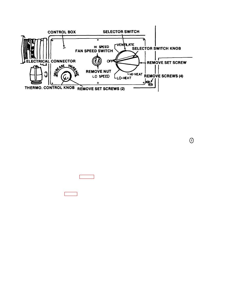
Figure 2-1 (1). Control panel, block-off plate, thermostat sensing bulb and control box back panel removal and installation. |
|
||
| ||||||||||
|
|
 TM 5-4120-273-15
NOTE: TAG AND DISCONNECT ELECTRICAL LEADS AS NECESSARY.
CONTROL PANEL:
STEP 1 - REMOVE THERMOSTAT CONTROL KNOB BY LOOSENING SETSCREW.
STEP 2 - REMOVE NUT FROM FAN SPEED SWITCH.
STEP 3 - REMOVE SELECTOR SWITCH KNOB BY LOOSENING SETSCREWS.
STEP 4 - UNSCREW ELECTRICAL CONNECTOR.
STEP 5 - REMOVE CONTROL BOX BY REMOVING SCREWS (4).
MEC 4120-273-15/2-1
control box back panel removal and installation.
Note. Remove discharge and intake grilles and filter,
d. Power Sources.
if unit is to be used with ducts carrying air to and from
the conditioned- space. Install grilles and filter into the
(1) Model CV-6-3-08-400. Operates on
duct.
208 volt, 400 cycle, 3 phase power.
(2) Model CV-6-1-15-60. Operates on 115
chemical and biological filter unit is to be attached to the
volts 50/60 cycle, single phase power.
unit.
c. Installing Unit. Bolt unit to floor or other
(3) Power receptacle connector. Receptacle
flat surface. Refer to base plan (fig. 1-4) for di-
is located at rear of unit above the condenser coil
mensions. An additional fastening device (fig.
air inlet. Connect the proper electrical power sup-
13) is provided on the upper rear side of the unit
ply source to this receptacle using a plug or recep-
for additional mounting rigidity if required. Con-
tacle alternate. Alternate electrical power connec-
nect drain hose to drain fitting at bottom of unit
tion openings are provided at both sides and front
to lead condensate away from unit. The units are
of the unit, any location may be used by inter-
provided with four drain plugs installed. Remove
changing the power receptacle at rear of the unit
plug prior to installing the drain hose.
and one of the cover plates at sides or front of the
2-2
|
|
Privacy Statement - Press Release - Copyright Information. - Contact Us |
