 |
|||
|
|
|||
|
|
|||
| ||||||||||
|
|
 TM 5-4120-273-15
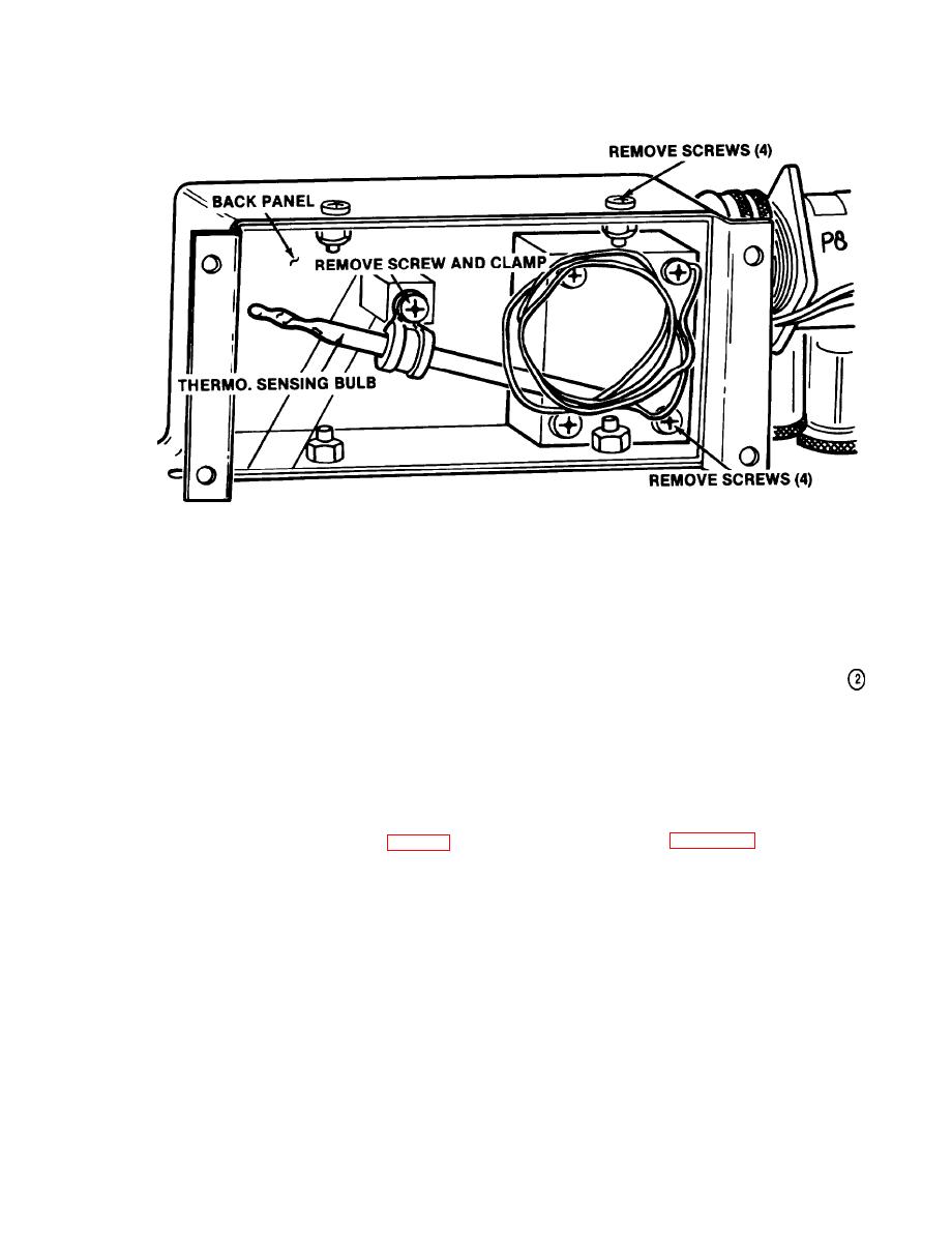
THERMOSTAT SENSING BULB:
STEP 1 - REMOVE THERMOSTAT SENSING BULB BY REMOVING
SCREW AND CLAMP.
STEP 2 - REMOVE BACK PANEL BY REMOVING SCREWS (4) AND
LOCKNUTS (4).
STEP 3- REMOVE THERMOSTAT BY REMOVING SCREWS (4).
MEC 4120-273-15/2-1
Figure 2-1 (2)--Continued
unit. Be sure to attach cover plate over unused lo-
at another location, thus allowing the air condi-
cation at rear of unit to prevent air from being
tioner to be controlled from this remote location.
drawn through the opening.
(2) Remote control connection.
(a) Disconnect power source from unit.
e. Remote Control.
(b) Refer to figure 2-1(1), 2-1(2), and
(1) General. The control box (fig. 2-1 (1))
2-1(3) for installing blockoff plate.
may be removed from the unit and used for remote
Note. A cable must be provided connecting the
control operation of the air conditioner. A block-
new remotely located control box and the block-off plate.
off plate provided as an accessory must be used to
replace the control box. The control box is placed
|
|
Privacy Statement - Press Release - Copyright Information. - Contact Us |
