 |
|||
|
|
|||
|
|
|||
| ||||||||||
|
|
 TM 9-4120-425-14&P
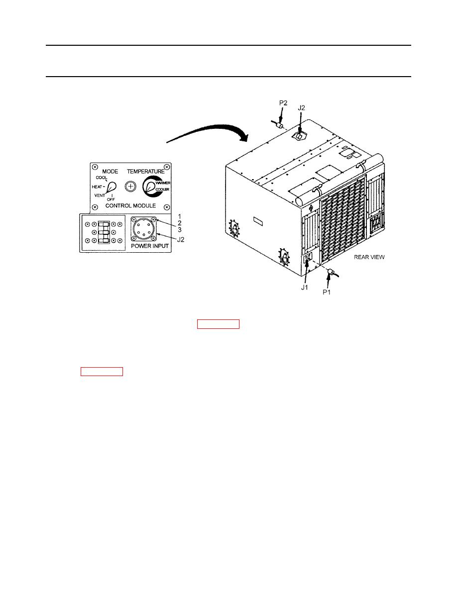
MAIN POWER INPUT CONNECTOR (J2) and ALTERNATE POWER INPUT
0043-00
CONNECTOR (J1) UNIT MAINTENANCE - Continued
INSPECTION Continued
NOTE
Use Schematic Diagram, WP 0122-00 for the following instructions.
REMOVAL
1.
Tag all wire leads prior to removal.
2.
Refer to WP 0033-00 for J2 connector removal.
3.
Remove four screws (1), four washers (2) and four nuts (3) to release each connector from housing.
4.
Disconnect all connector plugs , terminals and clamps.
NOTE
The J1 connector is routed thru two oversize clamps in the condenser section bottom
and bulkhead.
5.
Carefully remove harness from unit. Each connector has a separate harness.
TEST
1.
Test for continuity on wiring harness.
2.
Touch the test probes of a multimeter, set on low-resistance range, to ends of wire and/or corresponding pin of
connector.
3.
If continuity is not indicated, repair or replace wire or damaged connector.
0043-00-2
|
|
Privacy Statement - Press Release - Copyright Information. - Contact Us |
