
TM 10-8145-222-23
0014
SERVICE CONTINUED
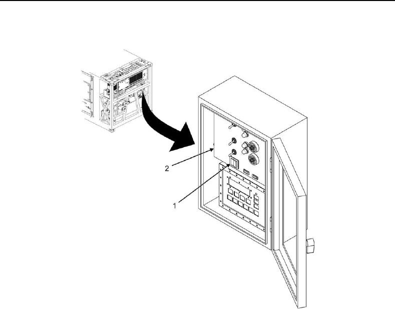
8. Place POWER DOWN/ON switch (Figure 3, Item 1) on control panel (Figure 3, Item 2) to DOWN position.
Figure 3. Control Panel.
9. Backseat suction (Figure 1, Item 1) and discharge (Figure 1, Item 2) service valves by turning counterclockwise.
10. Remove manifold gauges from compressor suction (Figure 1, Item 1) and discharge (Figure 1, Item 2) service
valves.
11. Close compressor suction service valve (Figure 1, Item 1) by turning clockwise and trap refrigerant between
compressor suction service valve (Figure 1, Item 1) and receiver outlet valve (Figure 2, Item 1).
12. Tag the MTRCS in accordance with unit standard operating procedures to indicate the system is pumped
down.