
TM 10-8145-222-23
0035
REPLACE CONTINUED
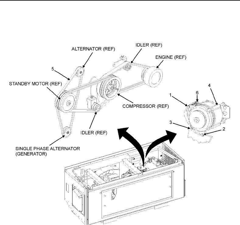
7. Loosen alternator self-locking nut (Figure 3, Item 1); lower mount bolt (Figure 3, Item 2) and V-belt tension
adjustment bolt (Figure 3, Item 3) enough that alternator (Figure 3, Item 4) is free to pivot.
8. Remove standby motor to single-phase alternator V-belt (Figure 3, Item 5).
Figure 3. Alternator V-Belt.
9. Place new standby motor to single-phase alternator V-belt (Figure 3, Item 5) around alternator, standby motor,
and single-phase alternator pulleys.
CAUTION
Excessive force when placing tension on the alternator V-belt may cause damage to
the alternator bearing. Use hand force only to apply tension. Do not use pry bar or
any other mechanical tool to apply tension to the alternator V-belt during installation
or adjustment procedures.
10. Use hand pressure to pivot alternator slightly outward to tighten V-belt (Figure 3, Item 3) in order to put 30-50
pounds tension on new alternator V-belt (Figure 3, Item 5).