
TM 10-8145-222-23
MAINTAINER MAINTENANCE
HEATER
REPLACE
INITIAL SETUP:
Tools and Special Tools
References
Service Refrigeration Ordnance
TM 10-8415-222-10
Tool Kit (WP 0096, Table 2, Item 6)
TM 10-8415-222-10
Electrical Connector Kit (WP 0096, Table 2, Item 3)
Personnel Required
Equipment Condition
Utilities Equipment Repairer
Refrigeration unit shut down (TM 10-8415-222-10)
External power cables disconnected (TM 10-8415-
222-10)
Battery disconnected (WP 0053)
REPLACE
NOTE
There are two evaporators located inside the MTRCS insulated container. Each of
the evaporators has three tubular electrical heaters. This procedure is applicable to
the replacement of either evaporator heater.
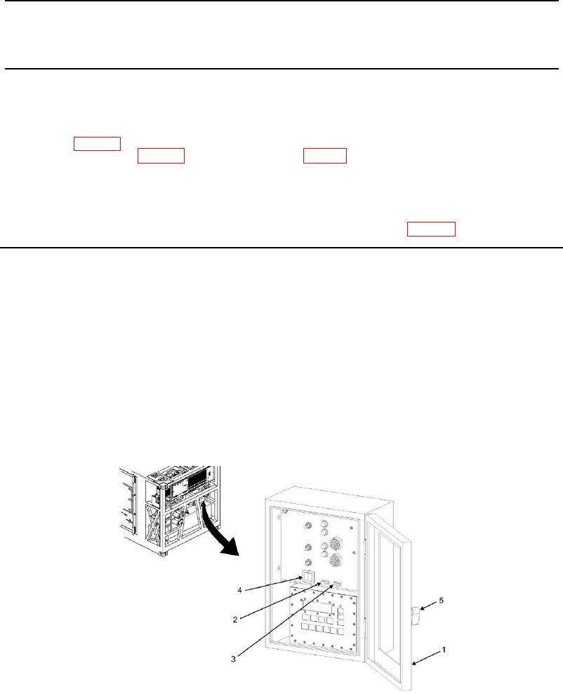
1. Open MTRCS control box door (Figure 1, Item 1).
2. On control box, place COMPARTMENT 1 ON/OFF rocker switch (Figure 1, Item 2) to OFF position.
3. Place COMPARTMENT 2 ON/OFF rocker switch (Figure 1, Item 3) to OFF position.
4. Place POWER ON/DOWN switch (Figure 1, Item 4) on control panel to DOWN position.
5. Close MTRCS control box door (Figure 1, Item 1) and latch (Figure 1, Item 5).