 |
|||
|
|
|||
|
Page Title:
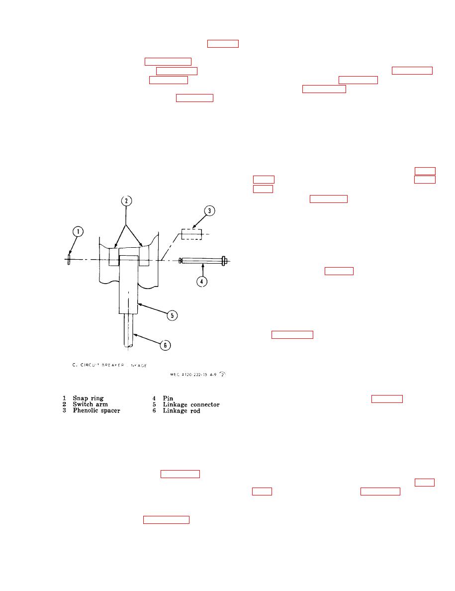
Figure 3-11. Circuit breaker linkage detail. |
|
||
| ||||||||||
|
|
 c. Installation. Install the rectifier, control box
installation). Test the circuit breaker for conti-
cover, and front access pane] by reversing the
nuity with a multimeter set on the ohm scale.
order of removal.
Refer to the applicable wiring diagram (fig. 1-3
or 14) for contact points.
c. Removal. Refer to figure 310 and remove
the circuit breaker. Refer to figure 3-11 and dis-
and control box cover (para 324).
the circuit breaker. Refer to figure 311 and dis-
b. Refer to figure 310 and remove the terminal
connect the circuit breaker leads as follows:
blocks.
(1) Remove snap ring (1, fig. 3-11) from
pin (4).
(2) Pull pin (4) and spacer (3) from switch
a. General. Both of the contractors are located
arm (2).
within the control box. The compressor contactor
(3) Remove linkage rod (6) and connector
starts the compressor and the heater contactor
(5).
energizes the heaters.
d. Installation. Install the circuit breaker, con-
b. Removal.
trol box cover, and front access cover by revers-
(1) Remove the front access panel (para
ing the order of removal.
(2) Refer to figure 3-10 and remove the con-
tractors.
c. Installation. Install the rectifier, control
box cover, and front access panel by reversing the
order of removal.
3-31. Outdoor Thermostat
a. General. The outdoor thermostat is mounted
to the rear housing (fig. 12) of the air condi-
tioner. It prevents the compressor from being
started when the outside air temperature is below
50 F. when low condensing and suction and suc-
tion pressures will hamper system operation.
b. Removal.
(1) Remove the condenser fan guard and
fan (para 319).
(2) Tag and disconnect electrical leads con-
necting the outdoor thermostat to the unit.
(3) Remove the two screws mounting ther-
mostat to housing. Remove outdoor thermostat.
with a multimeter set on the ohms scale. Refer to
the applicable wiring diagram (fig. 13/14) for
points to establish contact.
d. Installation. Install the outdoor thermostat,
fan and fan guard by reversing the order of re-
moval.
3-28. Rectifier
332. Fuse Service
a. Testing.
a. There are two 5ampere fuses located in the
(1) Remove the front access panel (para
control box in the upper right hand corner.
3-15) and control box cover (para 324).
(2) Using a multimeter, test the front and
back resistance of the rectifier. A resistance of in-
fuses from fuse holder and replace as required.
finity in both directions indicate an open rectifier
c. Installation. Install the control box cover
that must be replaced.
and front access panel by reversing the order of
removal.
the rectifier.
|
|
Privacy Statement - Press Release - Copyright Information. - Contact Us |
