 |
|||
|
|
|||
|
Page Title:
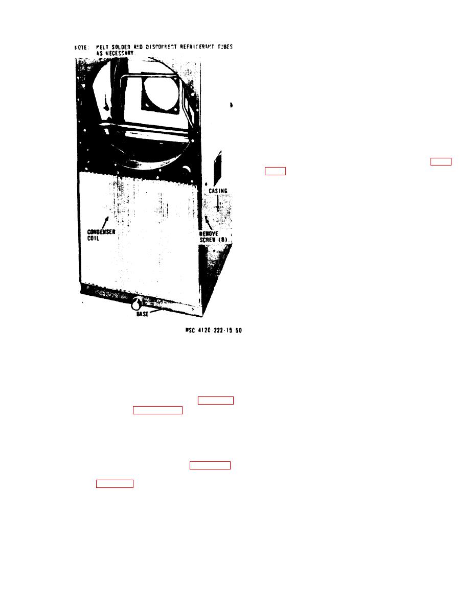
Figure 513. Condenser coil, removal and installation. |
|
||
| ||||||||||
|
|
 (2) Experience has demonstrated that after
a hermetic motor burnout the system must be
cleaned thoroughly to remove all contaminants;
otherwise a repeat burnout will occur. Failure to
follow these instructions as quickly as possible
will result in an excessive risk of a repeat bur-
nout, and damage to other system components.
b. Clean Up Procedure. Make certain that a
burnout has occurred. A motor that fails to start
may be due to improper voltage or a malfunction
of the motor starter, or a compressor mechanical
fault.
(1) To check for proper voltage, turn off the
main disconnect switch so that all power is off.
(2) Remove the front access panel (para
(3) Remove the compressor leads at the
compressor side of the starter.
(4) Close the disconnect switch to energize
the control circuit.
(5) Check for voltage on all lines at both
the line and load side of the starter.
make sure the compressor is cool to the touch. Otherwise a
false indication may be obtained due to internal motor
protectors being open.
(6) Check the compressor motor to see if it
is electrically grounded or open. A 500-volt meg-
ger or an ohmeter can be used for making the
test. Typical megger readings are 5 megohms for
R22. If no fault is found and if the normal values
for winding resistance are known, check and re-
cord stator currents for balance by the watt
meter or ohmeter method. Use rated meters.
occur. An appreciable unbalanced phase indicates a
shorted winding. Resistance should be checked with a pre-
Caution: Use rubber gloves when handling
cision ohmeter to determine if turn-to-turn shorts exist.
or cleaning the unit or surrounding area.
(7) Purge a small quantity of refrigerant
(3) Discharge the refrigerant (para 6-1).
gas from the compressor and smell it cautiously.
(4) Refer to figure 5-14 and remove the
A motor burnout is usually indicated by the cus-
compressor/motor unit. Use extreme care when
tomary burned odor.
sweating the connections loose.
c. Safety Measures. In addition to the electrical
d. Installation.
hazards, the serviceman should be aware of acid
(1) Install the compressor/motor unit by
burns.
reversing the order of removal.
(1) When testing for odor, release a small
(2) Replace the dehydrator (para 5-18).
amount of gas and smell it cautiously to avoid in-
(3) Evacuate and recharge the refrigerant
halation of toxic decomposition products.
system (para 6-1).
(2) When discharging gas or liquid refriger-
(4) Replace the front access panel (para
ant from a burnout, avoid eye or skin contact
3-15).
with the product. If the entire charge is to be re-
moved, it should be discharged outside any enclo-
Compressor/Motor Burnout Clean Up
sure. Do not discharge in the vicinity of open
Procedure
flame.
a. General.
(3) When necessary to come in contact with
(1) The scope of this procedure pertains to
oil or sludge from a burned out compressor, ap-
hermetic compressors.
5-17
|
|
Privacy Statement - Press Release - Copyright Information. - Contact Us |
