
TM 10-8145-222-23
MAINTAINER MAINTENANCE
EMERGENCY STOP SWITCH
REPLACE
INITIAL SETUP:
Tools and Special Tools
References
General Mechanic Tool Kit (WP 0096, Table 2, Item 5)
TM 10-8145-222-10
Materials/Parts
TM 10-8145-222-23P
Lock Washer (WP 0097, Item 11)
Equipment Condition
Personnel Required
Refrigeration unit shut down (TM 10-8145-222-10)
Quartermaster and Chemical Equipment Repairer
External power cables disconnected (TM 10-8145-
222-10)
REPLACE
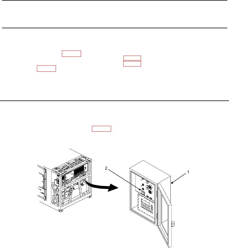
1. On control panel (Figure 1, Item 1), place POWER ON/DOWN switch (Figure 1, Item 2) to DOWN position.
2. Disconnect battery negative (-) terminal (WP 0053, Disconnect).
Figure 1. POWER ON/DOWN Switch.