
TM 10-8145-222-23
0030
REPLACE CONTINUED
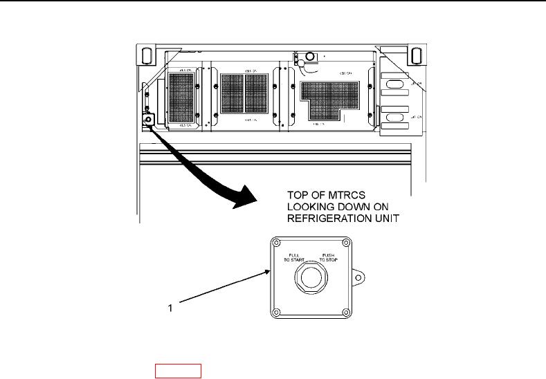
Figure 3. Emergency Stop Switch.
6. Remove top-middle panel (WP 0013, Remove).
7. Loosen alternator mounting bolts (Figure 4, Item 1 and Item 2) and self-locking nut (Figure 4, Item 3) enough
that the alternator (Figure 4, Item 4) is free to pivot. Do not remove at this time.
8. Screw alternator adjusting bolt (Figure 4, Item 5) counterclockwise until tension is off V-Belt (Figure 4, Item 6).
9. Push alternator (Figure 4, Item 4) downward to loosen alternator V-belt (Figure 4, Item 5).
10. Remove alternator V-belt (Figure 4, Item 6) from alternator pulley (Figure 4, Item 7).
11. Remove four bolts (Figure 4, Item 8), lock washers (Figure 4, Item 9), and stand-offs (Figure 4, Item 10)
securing alternator cover bracket (Figure 4, Item 11) to alternator (Figure 4, Item 4). Discard lock washers.
NOTE
It will be necessary to loosen strain relief nut in order to gain access to alternator wire
leads. Once the strain relief nut is loose, the alternator cover bracket cube slides
away from the alternator.
12. Loosen strain relief nut (Figure 4, Item 12) if necessary.
13. Remove nuts (Figure 4, Item 13) and washers (Figure 4, Item 14) from alternator (Figure 4, Item 4).