
TM 10-8145-222-23
0037
ADJUST CONTINUED
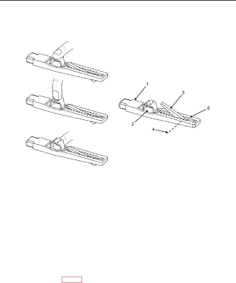
7. On tension gauge (Figure 5, Item 1), press slowly on black pad (Figure 5, Item 2) and stop when click is heard
or felt.
Figure 5. V-Belt Tension Gauge.
8. Carefully remove tension gauge (Figure 4, Item 1) from V-belt (Figure 4, Item 2) so that black indicator arm
(Figure 5, Item 3) is not moved.
9. Turn tension gauge (Figure 5, Item 1) sideways and mark position (Figure 5, Item 4) where black indicator arm
(Figure 5, Item 3) intersects scale (Figure 5, Item 5).
NOTE
The V-belt tension is determined by reading the scale at the exact location where the
black indicator arm intersects the scale on top of the gauge.
10. Turn tension gauge (Figure 5, Item 1) so that scale (Figure 5, Item 5) can be read, and determine V-belt
tension.
11. Adjust V-belt tension as needed to obtain required tension per this WP.
12. Recheck V-belt tension per steps 6-10 of this task.
13. Install top-middle panel (WP 0013, Install).
14. Place emergency stop switch (Figure 2, Item 1) in PULL TO START position.