
TM 10-8145-222-23
0052
TEST CONTINUED
5. Tag and disconnect wiring (Figure 1, Item 4) to switch S1 (Figure 1, Item 2) terminals S1-1, S1-5, and S1-9
(Figure 2).
6. Tag and disconnect wiring (Figure 1, Item 5) to transformer TR1 (Figure 1, Item 3) terminal TR1-X0 (Figure 3).
7. Tag ground wires leading to power box ground (GND) lug (Figure 1, Item 6).
8. Remove one power box ground lug (Figure 1, Item 6), lock washer (Figure 1, Item 7), washer (Figure 1, Item 8),
and screw (Figure 1, Item 9) securing three ground wires to power box (Figure 1, Item 10). Discard lock washer.
9. Disconnect ground wires and position disconnected ground wires away from transformer (Figure 1, Item 3).
Temporarily secure if needed.
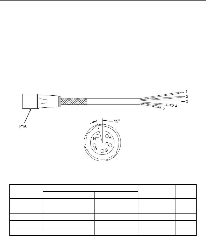
10. Use a multimeter set to ohms scale to make Cable Assembly P1A (Figure 4) continuity checks as shown in
Table 1.
Figure 4. Cable Assembly P1A and Contact Arrangement.
Table 1. Cable Assembly P1A.
Termination
Figure 4 Wire
Ref No.
Wire Color
Result
From
To
1
P1A-A
S1-1
Red
<0.5Ω
2
P1A-B
S1-5
Black
<0.5Ω
3
P1A-C
S1-9
Orange
<0.5Ω
4
P1A-N
TR1-X0
White
<0.5Ω
5
P1A-G
GND
Green
<0.5Ω
11. If Result column in Table 1 indicates greater than 0.5 ohm, perform cable assembly replace per this WP.