
TM 10-8145-222-23
0052
TEST CONTINUED
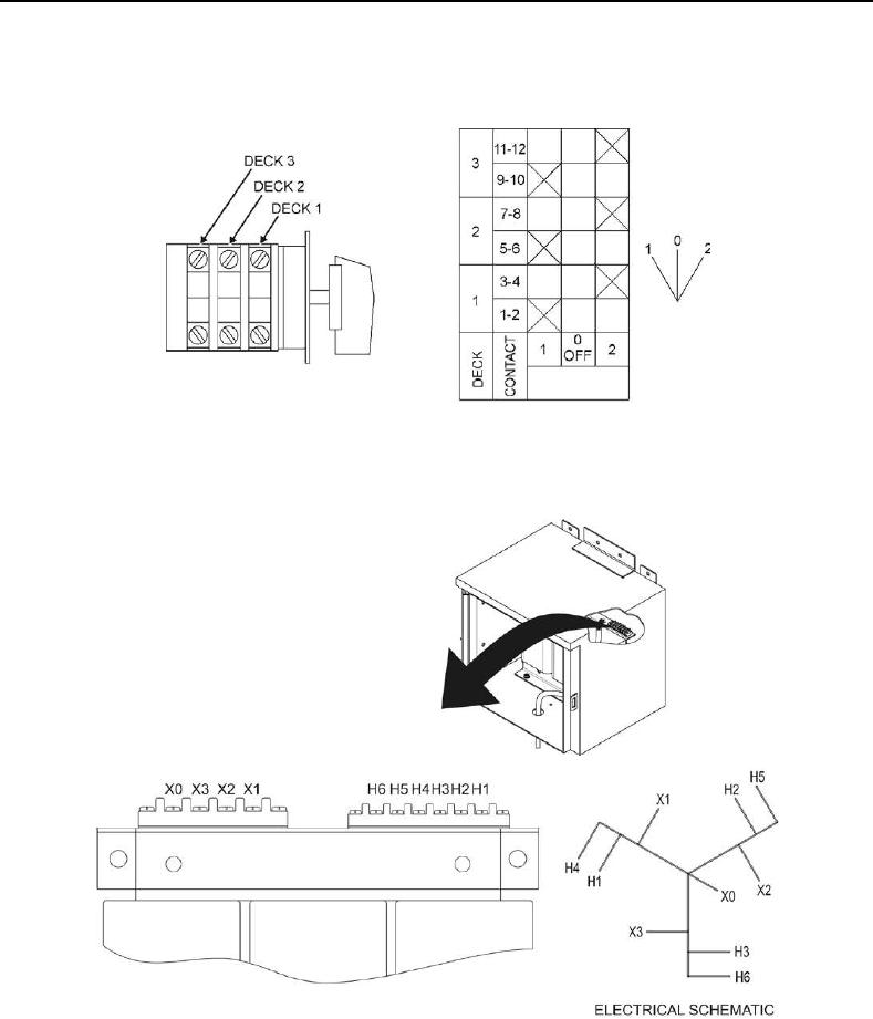
3. Use a multimeter set to AC voltage scale to verify no voltage is present on switch S1 (Figure 1, Item 2)
terminals S1-1, S1-5, and S1-9 (Figure 2).
Figure 2. Switch S1 and S2 Contact Arrangement and Circuit Diagram.
4. Use a multimeter set to AC voltage scale to verify no voltage is present on transformer TR1 (Figure 1, Item 3)
terminal TR1-X0 (Figure 3).
Figure 3. Transformer TR1 Layout and Circuit Diagram.