
TM 10-8145-222-23
0052
TEST CONTINUED
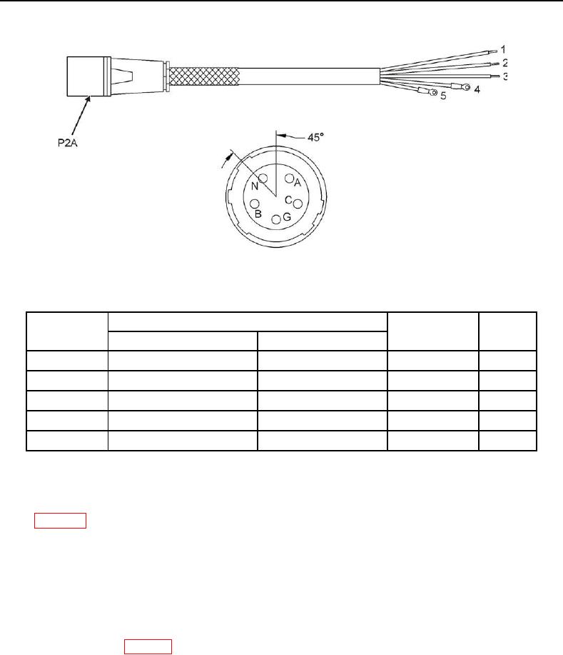
Figure 5. Cable Assembly P2A and Contact Arrangement.
Table 2. Cable Assembly P2A.
Termination
Figure 5 Wire
Ref No.
Wire Color
Result
From
To
1
P2A-A
S1-3
Red
<0.5Ω
2
P2A-B
S1-7
Black
<0.5Ω
3
P2A-C
S1-11
Orange
<0.5Ω
4
P2A-N
TR1-X0
White
<0.5Ω
5
P2A-G
GND
Green
<0.5Ω
11. If Results column in Table 2 indicates greater than 0.5 ohm, perform cable assembly repair per this WP.
12. Reconnect ground wires to power box (Figure 1, Item 10) using one screw (Figure 1, Item 9), washer (Figure 1,
Item 8), new lock washer (Figure 1, Item 7), and power box ground lug (Figure 1, Item 6). Tighten hardware
13. Reconnect wiring (Figure 1, Item 5) to transformer TR1 (Figure 1, Item 3) terminal TR1-X0 (Figure 3).
14. Reconnect wiring (Figure 1, Item 4) to switch S1 (Figure 1, Item 2) terminals S1-3, S1-7, and S1-11 (Figure 3).
15. Remove tags from wiring.
16. Close power box door (Figure 1, Item 1).
17. Reconnect battery (WP 0053, Reconnect).
18. Place MTRCS back into desired mode of operation (TM 10-8415-222-10, Operating Procedures).