
TM 10-8145-222-23
0052
REPLACE CONTINUED
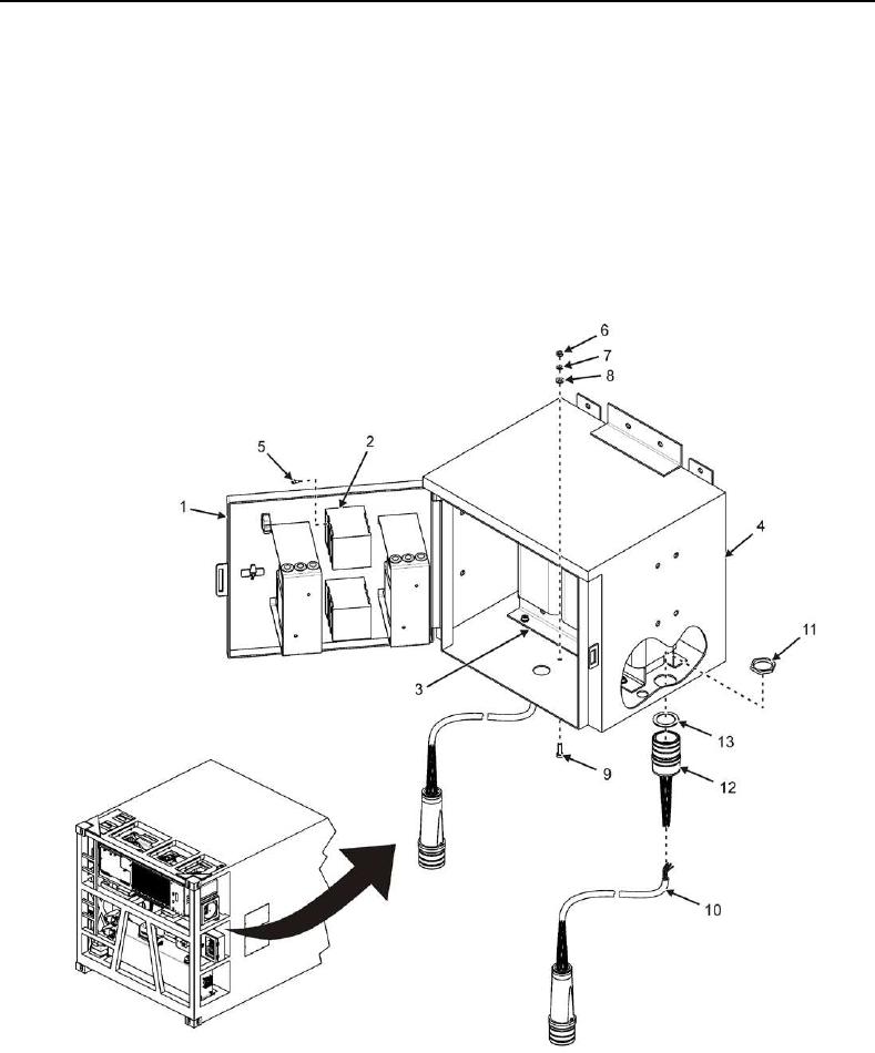
3. Open power box door (Figure 9, Item 1) and secure open.
4. Use a multimeter set to AC voltage scale to verify no AC voltage is present on switch S1 (Figure 9, Item 2)
terminals S1-1, S1-3, S1-5, S1-7, S1-9, and S1-11 (Figure 2).
5. Tag red wire terminating at switch S1 (Figure 9, Item 2) terminal S1-1 (Figure 2).
6. Tag black wire terminating at switch S1 (Figure 9, Item 2) terminal S1-5 (Figure 2).
7. Tag orange wire terminating at switch S1 (Figure 9, Item 2) terminal S1-9 (Figure 2).
8. Tag white wire terminating at transformer TR1 (Figure 9, Item 3) terminal TR1-X0 (Figure 3).
Figure 9. Power Cable Assembly P1A Replacement.