
TM 10-8145-222-23
0060
REPLACE CONTINUED
19. Desolder 1 1/8-inch pipe (Figure 7, Item 3) from accumulator (Figure 7, Item 4) at elbow (Figure 7, Item 5).
20. Desolder elbow (Figure 7, Item 5) from 1 1/8-inch pipe (Figure 7, Item 6). Discard elbow if installing a new
refrigeration unit. Retain elbow for reinstallation if removing refrigeration unit to facilitate other maintenance.
21. Desolder small lower refrigerant pipe (Figure 7, Item 7) at desolder location (Figure 7, Item 8).
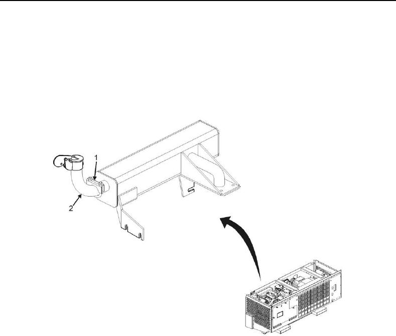
22. Loosen diesel engine muffler pipe U-bolt (Figure 8, Item 1) and remove muffler pipe (Figure 8, Item 2) to avoid
hitting it during refrigeration unit removal.
Figure 8. Muffler Pipe U-Bolt.