
TM 10-8145-222-23
0060
REPLACE CONTINUED
NOTE
There are four bolts securing the refrigeration unit to the container forward outside
wall at each corner, and three bolt and nut combinations securing the refrigeration
unit to the angle bracket at the forward lower end of the refrigeration unit. When
removing the bolts, remove the three support angle bolts first, followed by the bottom
two bolts on refrigeration unit, and the top two refrigeration unit mount bolts last.
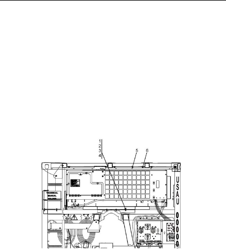
27. Unbolt support angle at front end near bale bar by removing three bolts (Figure 11, Item 1), lock washers
(Figure 11, Item 2), washers (Figure 11, Item 3), and nuts (Figure 11, Item 4).
28. Loosen 9 screws (Figure 11, Item 5) and lower seal bracket (Figure 11, Item 6) away from frame.
29. Position forklift tines inside refrigeration unit forklift slots (Figure 13) and carefully provide enough lift to support
refrigeration unit.
Figure 11. Support Angle Bolt Layout.