
TM 10-8145-222-23
0060
REPLACE CONTINUED
NOTE
The disconnect point of the braided line connector (P12/J12) can be identified by the
thin blue line around the portion of the connector that twists.
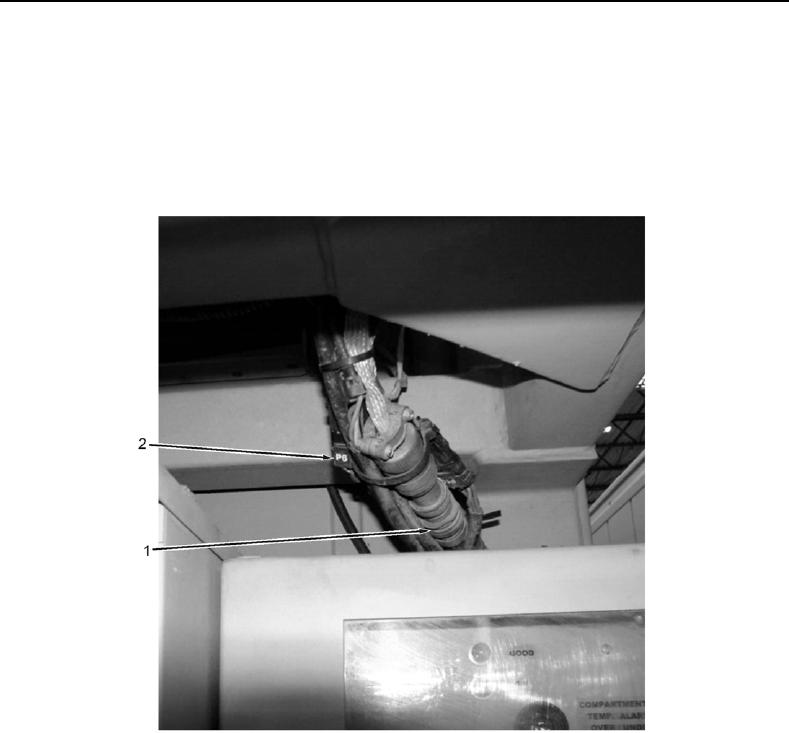
8. Tag and disconnect braided line connector (P12/J12) (Figure 3, Item 1) at control box.
9. Tag and disconnect power on/off connector (P6/J6) (Figure 3, Item 2) next to chart recorder.
Figure 3. Braided Line (P12/J12) and P6/J6 Connectors.