
TM 10-8145-222-23
0079
REPAIR CONTINUED
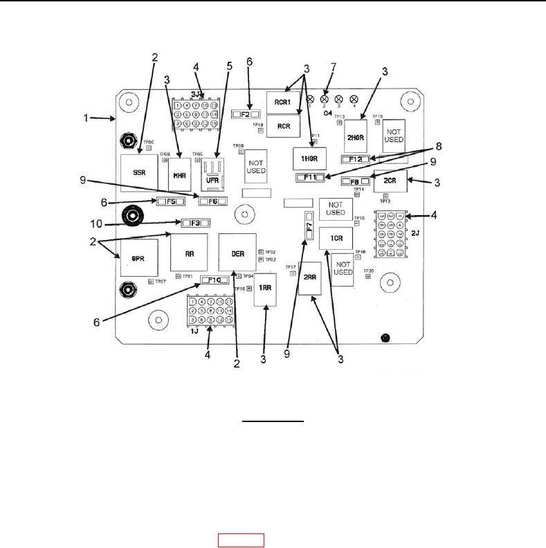
Figure 2. Microprocessor Control Box Door.
WARNING
Capacitors can store electrical power for extended periods of time after being
disconnected from power supply. A bleed resistor is connected across the capacitor
terminal to discharge this power more quickly. Do not touch capacitor terminals for
the first five minutes after the power has been disconnected.
NOTE
Schematics are in Microprocessor Control box.
1. Disconnect battery negative (-) terminal (WP 0053, Disconnect).
2. Remove pin and swing chart recorder out of the way.
3. Loosen two screws (Figure 3, Item 1) on Microprocessor Control (MPC) box cover (Figure 3, Item 2).
4. Open cover (Figure 3, Item 2).
5. Proceed to appropriate procedure below.