
TM 10-8145-222-23
0080
REPLACE CONTINUED
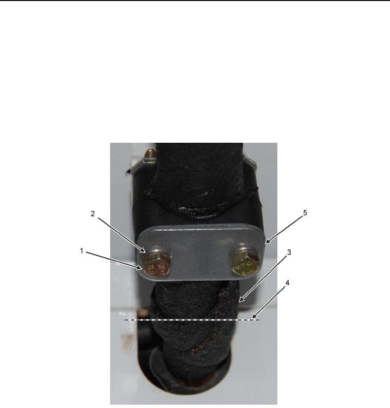
27. Remove two bolts (Figure 3, Item 1) and lock washers (Figure 3, Item 2) securing saddle clamp (Figure 3,
Item 5) to 7/8-inch evaporator pipe (Figure 3, Item 3).
28. Remove both halves of saddle clamp (Figure 3, Item 5). Retain for reinstallation.
29. Cut 7/8-inch refrigerant pipe (Figure 3, Item 3) at cut location (Figure 3, Item 4) midway between saddle clamp
bracket and cutout hole in evaporator.
Figure 3. 7/8-Inch Refrigerant Pipe Saddle Clamp.