• Home
  • Download PDF
  • Order CD-ROM
  • Order in Print
2. Unplug and remove relay (Figure 4, Item 2) from relay socket
Figure 6. Power Box and Control Panel Assembly Door.

TECHNICAL MANUAL FOR MULTI-TEMPERATURE REFRIGERATED CONTAINER SYSTEM
Page Navigation
  869    870    871    872    873  874  875    876    877    878    879  
img
.
TM 10-8145-222-23
0084
REPAIR CONTINUED
Replace Transformer TR1
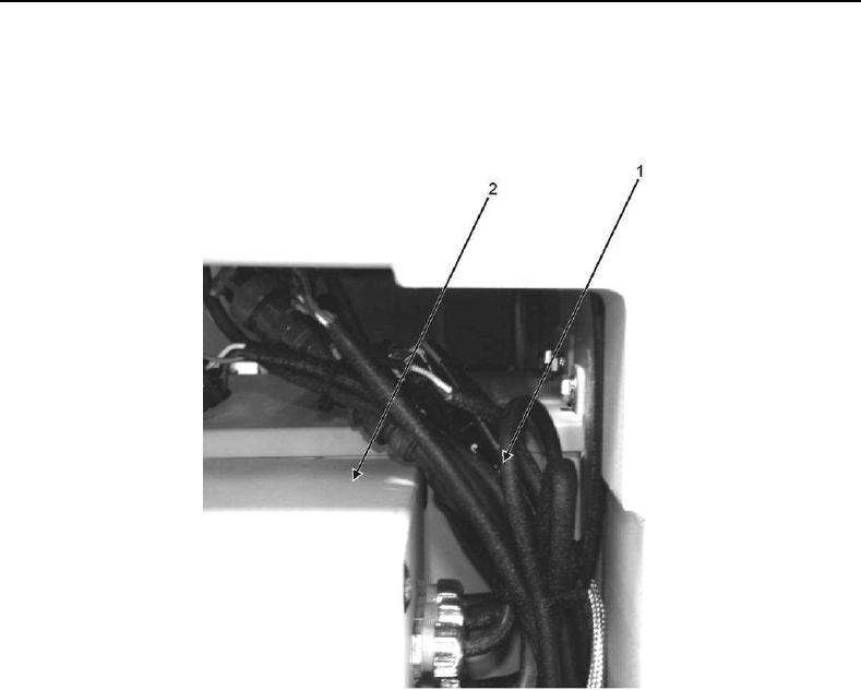
1. Locate wire bundle (Figure 5, Item 1) above control panel (Figure 5, Item 2) and cut tie wraps to gain access to
electrical connectors.
Figure 5. Control Panel Wire Bundle.
2. Tag and disconnect the following electrical connectors:
 P3/J3
 P4/J4
 P5/J5
 P6/J6
 P7/J7
 P8/J8
 P9/J9
 P10/J10
 P12/J12
 P13/J13
0084-9


Privacy Statement
Press Release
Contact

© Copyright Integrated Publishing, Inc.. All Rights Reserved.